

The OP AMP circuit shown in Figure P4=51 has the following input-output relationship: [ v_{mathrm{O}}=-frac{left(R_{mathrm{X}} R_{mathrm{Y}}+R_{mathrm{X}} R_{mathrm{Z}}+R_{mathrm{Y}}
Question:
The OP AMP circuit shown in Figure P4=51 has the following input-output relationship: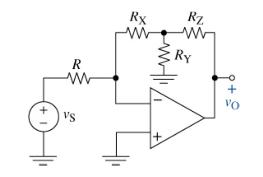 \[
\[
v_{\mathrm{O}}=-\frac{\left(R_{\mathrm{X}} R_{\mathrm{Y}}+R_{\mathrm{X}} R_{\mathrm{Z}}+R_{\mathrm{Y}} R_{\mathrm{Z}}ight)}{R R_{\mathrm{Y}}} v_{\mathrm{S}}
\]
\(R_{\mathrm{Y}}\) was accurately measured to be \(12.247 \mathrm{k} \Omega\). Select all the other resistors so that \(v_{\mathrm{O}}=-v_{\mathrm{S}}\).
Fantastic news! We've Found the answer you've been seeking!
Step by Step Answer:
First verfiy the inputoutput relationship Let U be the node voltage at the negat...View the full answer

Answered By
Sumedha Chakradeo
I have total 5 years experience in Industry as well as in teaching field.
I have Net teaching experience of 8 months. I have experience as Lecturer in different colleges in Pune.
I have worked as lecturer for around 2 years.
I have also NET exam of lectureship.
0 Reviews
10+ Question Solved
Related Book For 

The Analysis And Design Of Linear Circuits
ISBN: 9781119913023
10th Edition
Authors: Roland E. Thomas, Albert J. Rosa, Gregory J. Toussaint
Question Posted:
