

The output of a transistorized power supply is modeled by the Norton equivalent circuit shown in Figure
Question:
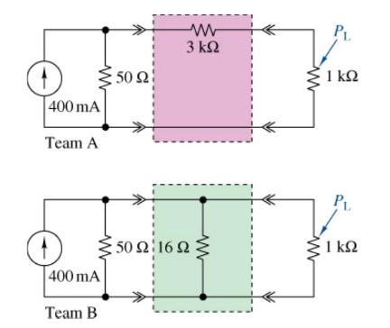
The output of a transistorized power supply is modeled by the Norton equivalent circuit shown in Figure P3=79. Two teams are competing to design the interface circuit so that \(25 \mathrm{~mW} \pm\) \(10 \%\) is delivered to the \(1-\mathrm{k} \Omega\) load resistor. Their designs are shown in Figure P3=79. Which solution is better considering the use of standard values, number of parts, and power required by the source? Would your choice be different if the power had to be within \(\pm 5 \%\) ?
Fantastic news! We've Found the answer you've been seeking!
Step by Step Answer:
Use current division to find the current supplied to the load in each design and then determi...View the full answer

Answered By
Krishnavendra Y
I am a self motivated financial professional knowledgeable in; preparation of financial reports, reconciling and managing accounts, maintaining cash flows, budgets, among other financial reports. I possess strong analytical skills with high attention to detail and accuracy. I am able to act quickly and effectively when dealing with challenging situations. I have the ability to form positive relationships with colleagues and I believe that team work is great key to performance. I always deliver quality, detailed, original (0% plagiarism), well-researched and critically analyzed papers.
4+ Reviews
10+ Question Solved
Related Book For 

The Analysis And Design Of Linear Circuits
ISBN: 9781119913023
10th Edition
Authors: Roland E. Thomas, Albert J. Rosa, Gregory J. Toussaint
Question Posted:
