

Question: Using base values of (20 mathrm{kVA}) and 115 volts in zone 3, rework Example 3.4. Example 3.4 Three zones of a single-phase circuit are identified
Using base values of \(20 \mathrm{kVA}\) and 115 volts in zone 3, rework Example 3.4.
Example 3.4
Three zones of a single-phase circuit are identified in Figure 3.10(a). The zones are connected by transformers \(T_{1}\) and \(T_{2}\), whose ratings are also shown. Using base values of \(30 \mathrm{kVA}\) and 240 volts in zone 1, draw the per-unit circuit and determine the per-unit impedances and the per-unit source voltage. Then calculate the load current both in per-unit and in amperes. Transformer winding resistances and shunt admittance branches are neglected.
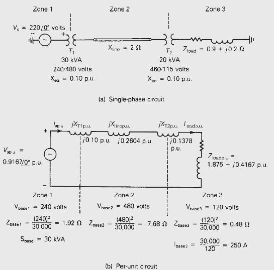
V = 220/0 volts Zone 1 V sp J. 0.9167/0 p.u. Zbase! 1038 = + Zone 1 Vbase1 = 240 volts (240) 30,000 Spase T 30 KVA 240/480 volts Xea = 0.10 p.u. lopujXT1p.u = = 30 KVA Zone 2 Xire 1.92 Zbase2 = 20 (a) Single-phase circuit. jXlinepuu. 10.10 p.u. 10.2604 p.u. = Zone 2 Vbasez = 480 volts T 20 kVA 460/115 volts Xeo = 0.10 p.u. (480) 30.000 7.68 (b) Per-unit circuit jXT2p.u. .. Zload = 0.9 + /0.1378 p.u. Zone 3 Zbase3 = bases = - 10.20 7 badp.u. 1.875 0.4167 p.u. Zone 3. Vase3 = 120 volts (120) 30,000 30,000 120 + = 0.48 250 A
Step by Step Solution
3.36 Rating (165 Votes )
There are 3 Steps involved in it

Get step-by-step solutions from verified subject matter experts