

Question: Using PowerWorld Simulator case Example 7_5, open the line connecting buses 4 and 5 . Then, determine the per unit current supplied by the generator
Using PowerWorld Simulator case Example 7_5, open the line connecting buses 4 and 5 . Then, determine the per unit current supplied by the generator at bus 3 due a fault at bus 2.
Example 7_5
PowerWorld Simulator case Example 7_5 models the 5-bus power system whose oneline diagram is shown in Figure 6.2. Machine, line, and transformer data are given in Tables 7.3, 7.4, and 7.5. This system is initially unloaded. Prefault voltages at all the buses are 1.05 per unit. Use PowerWorld Simulator to determine the fault current for three-phase faults at each of the buses.
Tables 7(3,4,5)
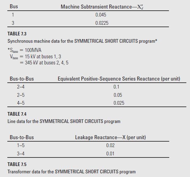
Bus 1 3 TABLE 7.3 Synchronous machine data for the SYMMETRICAL SHORT CIRCUITS program* *Stase = 100MVA Vbase = 15 kV at buses 1, 3 Machine Subtransient Reactance-X" 0.045 0.0225 = 345 kV at buses 2, 4, 5 Bus-to-Bus 2-4 2-5 4-5 Bus-to-Bus 1-5 3-4 Equivalent Positive-Sequence Series Reactance (per unit) 0.1 0.05 0.025 TABLE 7.4 Line data for the SYMMETRICAL SHORT CIRCUITS program Leakage Reactance-X (per unit) 0.02 0.01 TABLE 7.5 Transformer data for the SYMMETRICAL SHORT CIRCUITS program
Step by Step Solution
3.51 Rating (154 Votes )
There are 3 Steps involved in it

Get step-by-step solutions from verified subject matter experts