

Consider a plane truss in figure 1.31. The horizontal and vertical members have length (l), while inclined
Question:
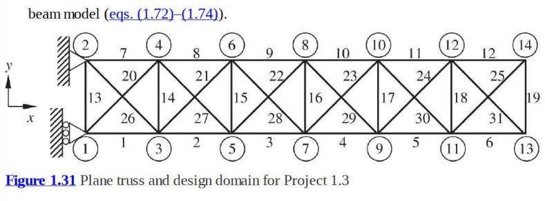
Consider a plane truss in figure 1.31. The horizontal and vertical members have length \(l\), while inclined members have length \(\sqrt{2} l\). Assume Young's modulus \(E=100 \mathrm{GPa}\), cross sectional area \(A=1.0 \mathrm{~cm}^{2}\), and \(l=0.3 \mathrm{~m}\).
i) Use an FE program to determine the deflections and element forces for the following three load cases. Present you results in the form of a table.
Load Case A) \(F_{x 13}=F_{x 14}=10,000 \mathrm{~N}\)
Load Case B) \(F_{y 13}=F_{y 14}=10,000 \mathrm{~N}\)
Load Case C) \(F_{x 13}=10,000 \mathrm{~N}\) and \(F_{x 14}=-10,000 \mathrm{~N}\)
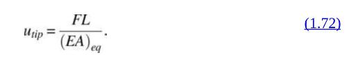
ii) Assuming that the truss behaves like a cantilever beam, one can determine the equivalent cross-sectional properties of the beam from the results for cases A through C above. The three beam properties are axial rigidity \((E A)_{e q}\) (this is different from the \(A E\) of the truss member), flexural rigidity \(\left(E I_{e q}\right.\), and shear rigidity \((G A)_{e q}\). Let the beam length be equal to \(L(L=6 \times 0.3=1.8 \mathrm{~m})\). The axial deflection of a beam due to an axial force \(F\) is given by:
The transverse deflection due to a transverse force \(F\) at the tip is:
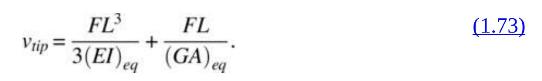
In eq. (1.73) the first term on the RHS represents the deflection due to flexure and the second term, due to shear deformation. In the elementary beam theory (Euler Bernoulli beam theory) we neglect the shear deformation, as it is usually much smaller than the flexural deflection.
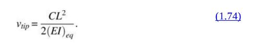
The transverse deflection due to an end couple \(C\) is given by:
Substitute the average tip deflections obtained in part 1 in eqs. (1.72)-(1.74) to compute the equivalent section properties: \((E A)_{e q},(E I)_{e q}\), and \((G A)_{e q}\).
You may use the average of deflections at nodes 13 and 14 to determine the equivalent beam deflections.
iii) Verify the beam model by adding two more bays to the truss \((L=8 \times 0.3=2.4 \mathrm{~m})\). Compute the tip deflections of the extended truss for the three load cases \(\mathrm{A}-\mathrm{C}\) using the FE program. Compare the FE results with deflections obtained from the equivalent
Step by Step Answer:


Introduction To Finite Element Analysis And Design
ISBN: 9781119078722
2nd Edition
Authors: Nam H. Kim, Bhavani V. Sankar, Ashok V. Kumar
