

The truss shown in figure 1.30 has two elements. The members are made of the aluminum hollow
Question:
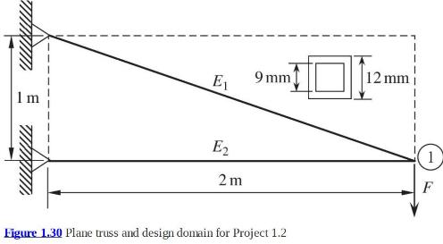
The truss shown in figure 1.30 has two elements. The members are made of the aluminum hollow square cross section. The outer dimension of the square is \(12 \mathrm{~mm}\), and the inner dimension is \(9 \mathrm{~mm}\). (The wall thickness is \(1.5 \mathrm{~mm}\) on all four sides.) Assume Young's modulus \(E=70 \mathrm{GPa}\), and yield strength \(\sigma_{Y}=70 \mathrm{MPa}\). The magnitude of the force at node 1 \((F)\) is equal to \(1,000 \mathrm{~N}\).
i) Use FEM to determine the displacements at node 1 and axial forces in elements 1 and 2.
Use von Mises yield theory to determine if the elements will yield or not. Use Euler buckling load ( \(P_{\mathrm{cr}}=\pi^{2} E I / L^{2}\) ) to determine if the elements under compressive loads will buckle. In the above expression, \(P_{c r}\) is the axial compressive force, \(E\) is Young's modulus, \(I\) is the moment of inertia of the cross section given by \(I=\left(a_{o}^{4}-a_{i}^{4}\right) / 12\), where \(a_{o}\) and \(a_{i}\), respectively, are the outer and inner dimensions of the hollow square cross section, and \(L\) is the length of the element.
ii) Redesign the truss so that both the stress and buckling constraints are satisfied with a safety factor of \(N\) not less than 2 for stresses, and \(N\) not less than 1.2 for buckling. Your design goal should be to reduce the weight of the truss as much as possible. The truss should be contained within the virtual rectangle shown by the dashed lines. Node 1 must be present to take the downward load \(F=1,000 \mathrm{~N}\). The nodes at the left wall have to be fixed completely. Nodes not attached to the wall have to be completely free to move in the \(x\) and \(y\) directions. Use the same cross section for all elements.
Calculate the mass of the truss you have designed. Assume the density of aluminum as \(2,800 \mathrm{~kg} / \mathrm{m}^{3}\). Draw the truss you have designed and provide the nodal coordinates and element connectivity in the form of a table. Results should also include the nodal displacements, forces in each member, and the safety factors for stresses and buckling for each element in the form of tables.
Step by Step Answer:

This question has not been answered yet.
You can Ask your question!

Introduction To Finite Element Analysis And Design
ISBN: 9781119078722
2nd Edition
Authors: Nam H. Kim, Bhavani V. Sankar, Ashok V. Kumar
