

The manufacturer of a heat flux gage like that illustrated in Problem 1 12 claims the time
Question:
The manufacturer of a heat flux gage like that illustrated in Problem 1 12 claims the time constant for a 63.2% response to be τ = (4d2 pc p) π2k where p, c p, and k are the thermo physical properties of the gage material and d is its thickness. Not knowing the origin of this relation, your task is to model the gage considering the two extreme cases illustrated below. In both cases, the gage, initially at a uniform temperature Ti, is exposed to a sudden change in surface temperature, T (0, t) = Ts- For case
(a) The backside of the gage is insulated, and for case
(b) The gage is imbedded in a semi-infinite solid having the same thermo physical properties as those of the gage.
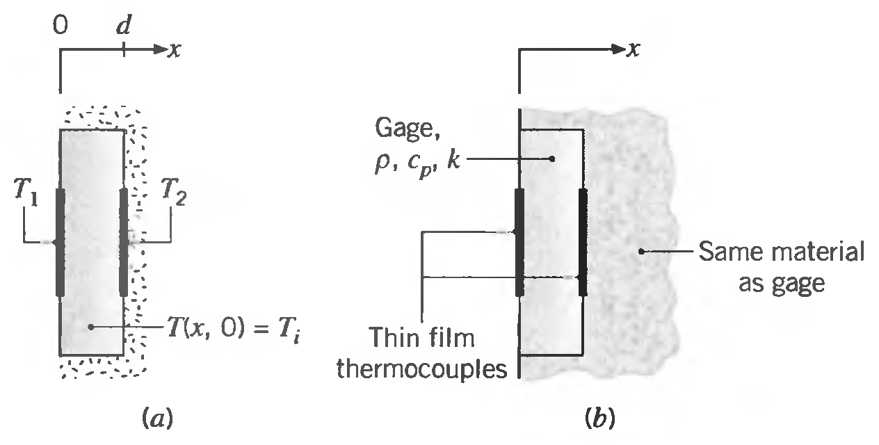
Develop relationships for predicting the time constant of the gage for the two cases and compare them to the manufacturer's relation. What conclusion can you draw from this analysis regarding the transient response of gages for different applications?
Step by Step Answer:
KNOWN Heat flux gage of prescribed thickness and thermophysical properties cp k initially at a unifo...View the full answer


Fundamentals of Heat and Mass Transfer
ISBN: 978-0471457282
6th Edition
Authors: Incropera, Dewitt, Bergman, Lavine
