

Question: A system such at that shown in Figure is used to convert balanced 50-Hz voltages to other frequencies. The synchronous motor has four poles and
A system such at that shown in Figure is used to convert balanced 50-Hz voltages to other frequencies. The synchronous motor has four poles and drives the interconnected shaft in the clockwise direction. The induction machine has six poles and its stator windings are connected to the source in such a fashion as to produce a counterclockwise rotating field (in the direction opposite to the rotation of the synchronous motor). The machine has a wound rotor whose terminals are brought out through slip rings.
a. At what speed does the motor run?
b. What is the frequency of the voltages produced at the slip rings of the induction motor?
c. What will be the frequency of the voltages produced at the slip rings of the induction motor if two leads of the induction-motor stator are interchanged, reversing the direction of rotation of the resultant rotatingfield?
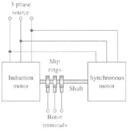
3-phase Source Slip rings Induction Synchronous Shaft motor motor Rotor terminals
Step by Step Solution
3.48 Rating (174 Votes )
There are 3 Steps involved in it
part a 1500 rmin part b The induction motor rotor is rotating ... View full answer

Get step-by-step solutions from verified subject matter experts
Document Format (1 attachment)
20-E-E-E-M (172).docx
120 KBs Word File