Figure shows a system consisting of a three-phase wound-rotor induction machine whose shaft is rigidly coupled to
Question:
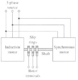
Figure shows a system consisting of a three-phase wound-rotor induction machine whose shaft is rigidly coupled to the shaft of a three-phase synchronous motor. The terminals of the three-phase rotor winding of the induction machine are brought out to slip rings as shown. With the system supplied from a three-phase, 60-Hz source, the induction machine is driven by the synchronous motor at the proper speed and in the proper direction of rotation so that three-phase, 120-Hz voltages appear at the slip rings. The induction motor has four-pole stator winding.
a. How many poles are on the rotor winding of the induction motor?
b. If the stator field in the induction machine rotates in a clockwise direction, what is the rotation direction of its rotor?
c. What is the rotor speed in r/min?
d. How many poles are there on the synchronous motor?
e. It is proposed that this system can produce dc voltage by reversing two of the phase leads to the induction motor stator. Is this proposalvalid?
Step by Step Answer:
part a Four poles part b Counterclockwise ...View the full answer