

Question: Consider the ratio control scheme shown in Fig. Each flow rate is measured using an orifice plate and a differential pressure (D/P) transmitter. The electrical
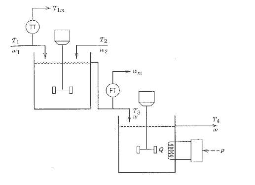
Consider the ratio control scheme shown in Fig. Each flow rate is measured using an orifice plate and a differential pressure (D/P) transmitter. The electrical output signals horn the D/P transmitters are related to the flow rates by the expressions.
Each transmitter output signal has a range of 4 to 20 mA. The transmitter spans are denoted by Sd and Su for the disturbance and manipulated flow rates, respectively. Derive an expression for the gain of the ratio station KR in terms of Sd, Su, and the desired ratioRd.
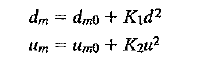
dm = dmo + Kd? Umo + Ku?
Step by Step Solution
3.30 Rating (162 Votes )
There are 3 Steps involved in it
By definition the ratio station sets Thus For constant ... View full answer

Get step-by-step solutions from verified subject matter experts
Document Format (1 attachment)
38-E-C-E-P-C (226).docx
120 KBs Word File