

Question: It is desired to control liquid level h 2 in the storage tank system shown in Fig by manipulating flow rate q 3 Disturbance variable
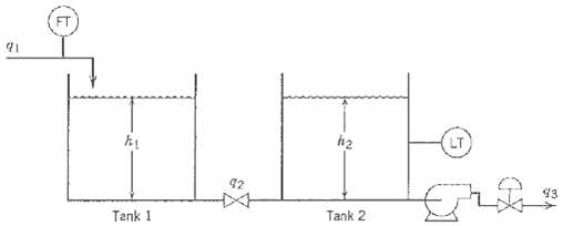
It is desired to control liquid level h2 in the storage tank system shown in Fig by manipulating flow rate q3 Disturbance variable q1 can be measured. Use the information available to do the following:
(a) Draw a block diagram for a feedforward feedback control system.
(b) Derive an ideal feedforward controller based on a steady-state analysis.
(c) Suppose that the flow-head relation for the hand valve is q2 = C?h1 ? h2. Does the ideal feedforward controller of part (b) change?
Available Information
(i) The two tanks have uniform cross-sectional areas, A1 and A2, respectively.
(ii) The valve on the exit line of Tank 1 acts as a linear resistance with a flow-head relation, q2 =?(h1 ? h2)/R.
(iii) The transmitters and control valve are pneumatic instruments that have negligible dynamics.
(iv) The pump operates so that flow rate q3 is independent of h2 when the control valve stem position is maintained constant.
42 43 Tank 1 Tank 2
Step by Step Solution
3.38 Rating (154 Votes )
There are 3 Steps involved in it
a The block diagram is the same as in Fig where Y ... View full answer

Get step-by-step solutions from verified subject matter experts
Document Format (1 attachment)
38-E-C-E-P-C (227).docx
120 KBs Word File