

Question: Design a digital controller for the liquid level in the storage system shown in Fig. E. Each tank is 2.5 ft in diameter. The piping
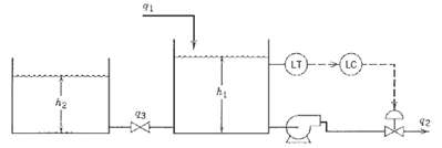
Design a digital controller for the liquid level in the storage system shown in Fig. E. Each tank is 2.5 ft in diameter. The piping between the tanks acts as a linear resistance to flow with R = 2 min/ft2. The liquid level is sampled every 30 s. The digital controller also acts as a zero-order hold device for the signal sent to the control valve. The control valve and level transmitter have negligible dynamics. Their gains are Kv = 0.25 ft3/min/mA and Km = 8 mA/ft, respectively. The nominal value of q1 is 0.5 ft3/min.
(a) Derive Dahlin?s control algorithm based on a step change in set point.
(b) Does the controller output exhibit any oscillation?
(c) For what values of ? is the controller physically realizable?
(d) If you were to tune this controller online, what value of ? would you use as an initial guess? Justify your answer.
LC 42 23
Step by Step Solution
3.50 Rating (183 Votes )
There are 3 Steps involved in it
a Material Balance for the tanks where A 1 A 2 p 425 2 491 ft 2 Using deviation variables and tak... View full answer

Get step-by-step solutions from verified subject matter experts
Document Format (1 attachment)
38-E-C-E-P-C (286).docx
120 KBs Word File