

Question: Figure shows a system for controlling the angular position of a load, such as an antenna. Figure shows the block diagram for PD control of
Figure shows a system for controlling the angular position of a load, such as an antenna. Figure shows the block diagram for PD control of this system using a field-controlled motor. Use the following values:
Ka = 1 V/V
R = 0.3 Ω
KT = 0.6 N.m/A
Kpot = 2 V/rad
I1 = 0.01 kg.m2
I2 = 5 x l0-4 kg.m2
l3 = 0.2 kg.m2
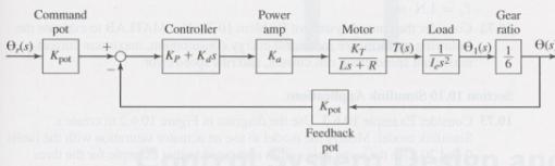
The inertia Ie in the block diagram is the equivalent inertia of the entire system, as felt on the motor shaft.
a. Assume that the motor inductance is very small and set L = 0. Compute Ie, obtain the transfer function Ɵ(s)/Ɵr(s), and compute the values of the control gains Kp and Kd to meet the following specifications: ζ = I and τ = 0.5 s.
b. Use the MATLAB t f function to create the model sys l from this transfer function.
c. Using the values of Kp and Kd computed in part (a), and the value L = 0.015 H, obtain the transfer function Ɵ(s)/Ɵr(s) and use the MATLAB t f function to create the model sys 2 from this transfer function.
d. Use the MATLAB step (sys l, sys2) function to plot the unit step response of both transfer functions. Right-click on the plots to obtain the maximum percent overshoot and settling time for each how close are the two responses? What is the effect of neglecting the inductance?
In Problem 7
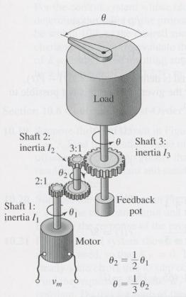
Command pot Power amp Gear ratio Controller Motor Load 0(s) O(x Ls +R not Feedback pot Load Shaft 2: inertia 3:1 0 Shaft 3: inertia l 02 Shaft inertia / Feedback pot Motor 02 3
Step by Step Solution
3.53 Rating (160 Votes )
There are 3 Steps involved in it
Let K K pot K a K T 6I e Where I e I 1 14I 2 19 I 3 00157 And K 127547 The transf... View full answer

Get step-by-step solutions from verified subject matter experts
Document Format (1 attachment)
755-C-D-S-D (625).docx
120 KBs Word File