

Question: Figure shows a configuration that can be used to measure the magnetic characteristics of electrical steel. The material to be tested is cut or punched
Figure shows a configuration that can be used to measure the magnetic characteristics of electrical steel. The material to be tested is cut or punched into circular laminations which are then stacked (with interspersed insulation to avoid eddy-current formation). Two windings are wound over this stack of laminations: the first, with N1 turns, is used to excite a magnetic field in the lamination stack; the second, with N2 turns, is used to sense the resultant magnetic flux. The accuracy of the results requires that the magnetic flux density be uniform within the laminations. This can be accomplished if the lamination width t = Ro ??? Ri is much smaller than the lamination radius and if the excitation winding is wound uniformly around the lamination stack. For the purposes of this analysis, assume there are n laminations, each of thickness ?. Also assume that winding 1 is excited by a current il = I0 sin wt.
a. Find the relationship between the magnetic field intensity H in the laminations and current i l in winding 1.
b. Find the relationship between the voltage v2 and the time rate of change of the flux density B in the laminations.
c. Find the relationship between the voltage v0 = G f v2 dt and the flux density. In this problem, we have shown that the magnetic field intensity H and the magnetic flux density B in the laminations are proportional to the current il and the voltage v2 by known constants. Thus, B and H in the magnetic steel can be measured directly, and the B-H characteristics as discussed in Sections 1.3 and 1.4 can be determined.
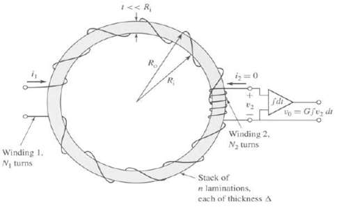
1 < < R, iz=0 Sdi o= Gftz dt Winding 2, Na turns Winding 1. Ny turns Stack of n laminations, cach of thickness A
Step by Step Solution
3.49 Rating (166 Votes )
There are 3 Steps involved in it
part a part b p... View full answer

Get step-by-step solutions from verified subject matter experts
Document Format (1 attachment)
20-E-E-E-M (25).docx
120 KBs Word File