

Question: In the generalized operational amplifier circuit shown in figure, Z 1 , Z 2 and Z 3 are impedances. The operational amplifier has an input
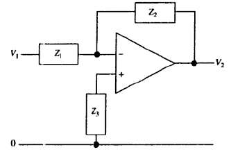
In the generalized operational amplifier circuit shown in figure, Z1, Z2 and Z3 are impedances. The operational amplifier has an input impedance greater than 10 M? and a gain equal to up to 100 Hz but inversely proportional to frequency at higher frequencies.
(a) It Z1 = 1 k? and Z2 = 100 k?, draw a graph to show how the voltage ratio V2/V1 varies with frequency.
(b) If Z1 = 1 k? and Z2 consists of a parallel combination of a resistor R2 = 10 k? and a capacitor C = I ?F, draw a graph to show how V2/V1?varies with frequency.
Z, V2
Step by Step Solution
3.47 Rating (176 Votes )
There are 3 Steps involved in it
We will entirely neglect the input impedance of the operational amplifier so t... View full answer

Get step-by-step solutions from verified subject matter experts
Document Format (1 attachment)
40-P-E-E-C (186).docx
120 KBs Word File