

Question: For the circuit of Fig. 9.41, parameter values are R F = 5 kΩ, R E = 50 Ω, and C F = 1.5 pF.
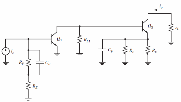
For the circuit of Fig. 9.41, parameter values are RF= 5 kΩ, RE= 50 Ω, and CF= 1.5 pF. The basic amplifier of the circuit is shown in Fig. 9.42 and has two negative real poles with magnitudes 3 MHz and 6 MHz. The low-frequency current gain of the basic amplifier is 4000. Assuming that the loop gain of the circuit of Fig. 9.41 can be varied without changing the parameters of the basic amplifier, sketch root loci for this circuit as f varies from 0 to 0.01 both with and without CF. Estimate the pole positions of the current-gain transfer function of the feedback amplifier of Fig. 9.41 with the values of RFand REspecified both with and without CF. Sketch graphs in each case of gain magnitude versus frequency on log scales from f = 10 kHz to f = 100 MHz.
Figure 9.41:
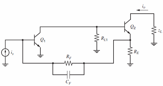
Figure 9.42:
Q2 RE Rp Cf w- Q2 Q1 R11 RE CF RF is CF Rf E RE
Step by Step Solution
3.42 Rating (165 Votes )
There are 3 Steps involved in it
Zero freq Z 1R F C F 150001510 12 133 10 8 radsec f z 212 MHZ Without C f For f 001 a o f 40 and p... View full answer

Get step-by-step solutions from verified subject matter experts
Document Format (2 attachments)
1528_605d88e1c65be_687082.pdf
180 KBs PDF File
1528_605d88e1c65be_687082.docx
120 KBs Word File