

Question: The transistor shown in Fig. 2.74 is connected in the circuit shown in Fig. 2.75. The gate is grounded, the substrate is connected to 1.5
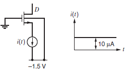
The transistor shown in Fig. 2.74 is connected in the circuit shown in Fig. 2.75. The gate is grounded, the substrate is connected to ˆ’1.5 V, and the drain is open circuited. An ideal current source is tied to the source, and this source has a value of zero for t < 0 and 10 _A for t > 0. The source and drain are at an initial voltage of+1.5Vat t = 0. Sketch the voltage at the source and drain from t = 0 until the drain voltage reachesˆ’1.5V. For simplicity, assume that the source substrate and drain-substrate capacitances are constant at their zero-bias values. Assume the transistor has a threshold voltage of 0.6 V.
Fig. 2.74
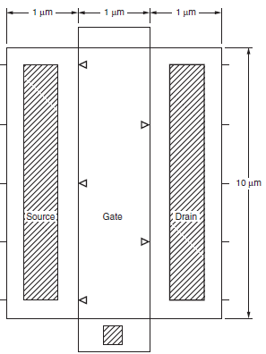
Fig. 2.75
1 - 1 um 1 um 10 m Source: Drain Gate i(t) 110 -1.5 V
Step by Step Solution
3.38 Rating (170 Votes )
There are 3 Steps involved in it
V D t 0 V s t 0 15 v i Intially transistor is off current source discharges C oL C SB ... View full answer

Get step-by-step solutions from verified subject matter experts
Document Format (2 attachments)
1528_605d88e1ab3a1_686798.pdf
180 KBs PDF File
1528_605d88e1ab3a1_686798.docx
120 KBs Word File