

Question: Draw a plot of elevation head, pressure head, velocity head, and total head for the siphon system shown in Fig. 6. 27 and analyzed in
Problem 6.72
For siphon shown in Fig. 6.27, calculate (1) the volume flow rate of oil from the tank and (b) the pressures at points A, B, C, and D.
Figure 6.27
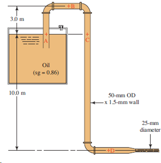
+B 3.0 m Oil l (sg = 0.86) 10.0 m 50-mm OD -x 1.5-mm wall 25-mm diameter
Step by Step Solution
★★★★★
3.47 Rating (176 Votes )
There are 3 Steps involved in it
1 Expert Approved Answer
Step: 1 Unlock

Plot shown below Data computed follows Pt 1 Tank surface Pt 2 ... View full answer
Question Has Been Solved by an Expert!
Get step-by-step solutions from verified subject matter experts
Step: 2 Unlock
Step: 3 Unlock