

Question: For the 1½ Ã 3 - 13 centrifugal pump performance curve shown in Fig. 13.34, determine the capacity that can be expected from a pump
Fig. 13.34
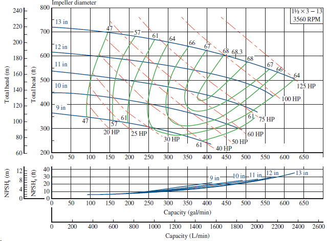
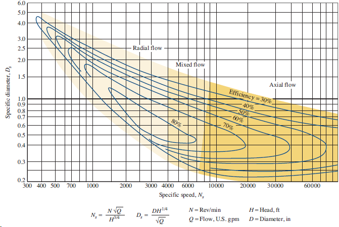
Fig. 13.53
Impeller diameter 800 240- |11 3 13 3560 RPM F13 in 220 700 61 64 200 66 F12 in 68 68.3 600 180 68 11 in 66 64 160 I 500 10 in 125 HP 140 100 HP 400 120 9 in 61 75 HP 61 57 20 HP 47 100 300 25 HP 60 HP 80 30 50 HP 61 40 HP 200 60 50 100 150 200 250 300 350 400 450 500 550 600 650 40 13 in 12 in 10 in 11 in 30 9 in' 20 10 50 100 150 200 250 300 350 400 450 500 550 600 650 Capacity (gal/min) 1600 2400 200 400 600 800 1000 1200 1400 1800 2000 2200 2600 Capacity (L/min) Total head (m) (u) HSAN Total head (ft) (u) 'HSAN 6.0 5.0 4.0 3.0 Radial flow 25 Mixed flow 2.0 Axial flow 1.5 Efficiency = 30% 40% 50% 60% 1.0 0.9 0.8 0.7 80% 70% 0.6 0.5 0.4 0.3 30000 60000 6000 10000 20000 0.2 300 400 500 2000 3000 4000 700 1000 Specific speed, N, H=Head, ft N= Rev/min N VQ 4314 DH4 D, = N, = Q=Flow, U.S. gpm D=Diameter, in Specific diameter, D,
Step by Step Solution
3.45 Rating (165 Votes )
There are 3 Steps involved in it
Point in Fig 1353 lies in radi... View full answer

Get step-by-step solutions from verified subject matter experts