

Question: Using the configuration established in Prob. 11-16, obtain a flowchart (similar to Fig. 11-11) for the CPU program to output data. Prob. 11-16 Show a
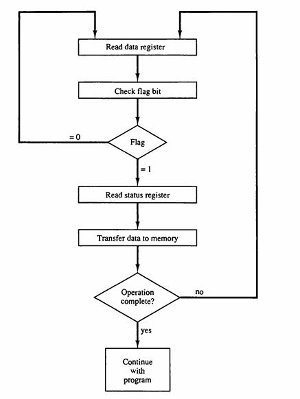
Using the configuration established in Prob. 11-16, obtain a flowchart (similar to Fig. 11-11) for the CPU program to output data.
Prob. 11-16
Show a block diagram similar to Fig. 11-10 for the data transfer from a CPU to an interface and then to an I/O device. Determine a procedure for setting and clearing the flag bit.
Fig. 11-10
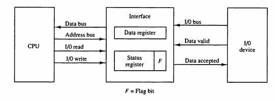
Fig. 11-11
CPU Data bus Address bus 1/0 read 1/0 write Interface Data register Status register F = Flag bit F 1/0 bus Data valid Data accepted I/O device
Step by Step Solution
3.46 Rating (149 Votes )
There are 3 Steps involved in it
Procedure for Setting and Clearing the Flag Bit 1 CPU check the flag bit before writing the data ... View full answer

Get step-by-step solutions from verified subject matter experts