

Question: A variable resistor, called a potentiometer, is shown in Figure. The resistance is varied by moving a wiper arm along a fixed resistance. The resistance
A variable resistor, called a potentiometer, is shown in Figure. The resistance is varied by moving a wiper arm along a fixed resistance. The resistance from A to C is fixed, but the resistance from B to C varies with the position of the wiper arm. If it takes 10 turns to move the wiper arm from A to C, draw a block diagram of the potentiometer showing the input variable, the output variable, and (inside the block) the gain, which is a constant and is the amount by which the input is multiplied to obtain the output. An animation PowerPoint presentation (PPT) demonstrating this system is available for instructors at www.wiley.com/college/nise.
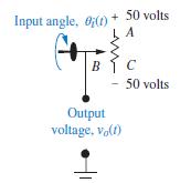
Input angle, O(t) + 50 volts B 50 volts Output voltage, vo(1)
Step by Step Solution
3.39 Rating (174 Votes )
There are 3 Steps involved in it
Lets answer your potentiometer block diagram question step by step Step 1 Understanding the System Input Variable The input is the angle of the wiper ... View full answer

Get step-by-step solutions from verified subject matter experts
Document Format (2 attachments)
2098_61d6ac3453097_865291.pdf
180 KBs PDF File
2098_61d6ac3453097_865291.docx
120 KBs Word File