Figure P7.31 shows the block diagram of the speed control of an HEV taken from Figure P5.53,
Question:
Figure P7.31 shows the block diagram of the speed control of an HEV taken from Figure P5.53, and rearranged as a unity feedback system (Preitl, 2007). Here the system output is C(s) = KSSV(s), the output voltage of the speed sensor/transducer.
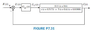
a. Assume the speed controller is given as GSC(s) = KPSC . Find the gain, KPSC , that yields a steady-state error, estep(∞) = 1%.
b. Now assume that in order to reduce the steady-state error for step inputs, integration is added to the controller yielding GSC(s) = KPSC + (KISC/s) = 100 + (KISC/s)). Find the value of the integral gain, KISC , that results in a steady-state error, eramp(∞) = 2.5%.
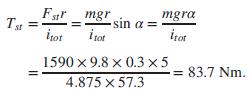
c. In Parts a and b, the HEV was assumed to be driven on level ground. Consider the case when, after reaching a steady-state speed with a controller given by GSC(s) = 100 + 40/s, the car starts climbing up a hill with a gradient angle, α = 5°. For small angles sin α = α (in radians) and, hence, when reflected to the motor shaft the climbing torque is
The block diagram in Figure P7.32 represents the control system of the HEV rearranged for Part c.
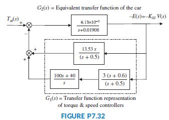
In this diagram, the input is Tst(t) = 83.7 u(t), corresponding to α = 5°, and the output is the negative error, -e(t) = -c(t) = -KSSv(t), proportional to the change in car speed, v(t). Find the steady-state error e(∞) due to a step change in the disturbance; e.g., the climbing torque, Tst(t) = 83.7 u(t).
Step by Step Answer: