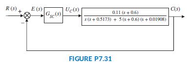
In Problem 67, Chapter 7 (Figure P7.31), the block diagram of a cascade scheme for the speed
Question:
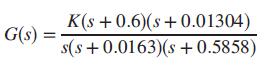
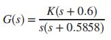
In Problem 67, Chapter 7 (Figure P7.31), the block diagram of a cascade scheme for the speed control of an HEV (Preitl, 2007) was represented as a unity feedback system. In that diagram the output of the system is the speed transducer’s output voltage, C(s) = KssV(s). In Part b of Problem 33, Chapter 11, where a compensator was designed for this problem, we discussed the feasibility of achieving full pole-zero cancellation when we place a PI speed controller’s zero, ZI, on top of the uncompensated system’s real pole, closest to the origin (located at-0.0163).Noting that perfect pole-zero cancellation may not be maintained, we studied a case where the PI-controller’s zero changed by +20%, moving to -0.01304. In that case, the transfer function of the plant with a PI speed controller, which has a proportional gain = K, was given by
Assuming that G1(s) in Figure P13.5 equals the transfer function, G(s), given above for the vehicle with the speed controller:
a. Develop a MATLAB M-file that would allow you to do the following:
(1) Convert G1(s) cascaded with a sample-and-hold to G(z);
(2) Search over the range 0 < T < 5 seconds for the largest sampling period T max below which the system is stable. Calculate the z-plane roots of theclosed loop system for the whole range of the sampling time, T. Subsequently set T = 0:75Tmax;
(3) Design the gain of a digital control system to meet a percent overshoot requirement, %OS, allowing the user to input the value of the desired %OS and the value of the PI speed controller’s proportional gain, K;
(4) Plot the step response of that digital system (in per unit, p. u., vs. time in seconds).
b. Run the M-file you developed in Part a and enter the values of the desired percent overshoot, %OS = 0, and the PI speed controller’s proportional gain, K = 61;
c. Select a point in the graphics window displaying the root locus, such that all poles of the closed-loop transfer function, Tz, are inside the unit circle.
d. Write the sampled-data transfer functions obtained, Gz and Tz, indicating the corresponding value of the sampling time, T, and all poles, r, of the closed-loop transfer function, Tz;
e. Plot the step response of that digital system (in per unit, p. u., vs. time in seconds) noting the following characteristics: final value, rise time, and settling time.
Data From Problem 67, Chapter 7:
Figure P7.31 shows the block diagram of the speed control of an HEV taken from Figure P5.53, and rearranged as a unity feedback system (Preitl, 2007). Here the system output is C(s) = KSSV(s), the output voltage of the speed sensor/transducer.
a. Assume the speed controller is given as GSC(s) = KPSC . Find the gain, KPSC , that yields a steady-state error, estep(∞) = 1%.
b. Now assume that in order to reduce the steady-state error for step inputs, integration is added to the controller yielding GSC(s) = KPSC + (KISC/s) = 100 + (KISC/s)). Find the value of the integral gain, KISC , that results in a steady-state error, eramp(∞) = 2.5%.
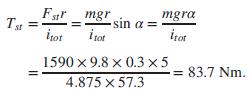
c. In Parts a and b, the HEV was assumed to be driven on level ground. Consider the case when, after reaching a steady-state speed with a controller given by GSC(s) = 100 + 40/s, the car starts climbing up a hill with a gradient angle, α = 5°. For small angles sin α = α (in radians) and, hence, when reflected to the motor shaft the climbing torque is
The block diagram in Figure P7.32 represents the control system of the HEV rearranged for Part c.
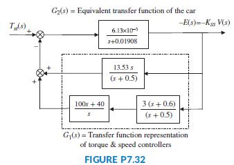
In this diagram, the input is Tst(t) = 83.7 u(t), corresponding to α = 5°, and the output is the negative error, -e(t) = -c(t) = -KSSv(t), proportional to the change in car speed, v(t). Find the steady-state error e(∞) due to a step change in the disturbance; e.g., the climbing torque, Tst(t) = 83.7 u(t).
Data From Problem 33, Chapter 11:
In Part b of Problem 54 in Chapter 10, we used a proportional-plus-integral (PI) speed controller that resulted in an overshoot of 20% and a settling time, Ts = 3:92 seconds (Preitl, 2007).
a. Now assume that the system specifications require a steady-state error of zero for a step input, a ramp input steady-state error ≤2%, a %OS ≤4.32%, and a settling time ≤4 seconds. One way to achieve these requirements is to cancel the PI-controller’s zero, ZI, with the real pole of the uncompensated system closest to the origin (located at -0.0163). Assuming exact cancellation is possible, the plant and controller transfer function becomes
Design the system to meet the requirements. You may use the following steps:
i. Set the gain, K, to the value required by the steady state error specifications. Plot the Bode magnitude and phase diagrams.
ii. Calculate the required phase margin to meet the damping ratio or equivalently the %OS requirement, using Eq. (10.73). If the phase margin found from the Bode plot obtained in Step i is greater than the required value, simulate the system to check whether the settling time is less than 4 seconds and whether the requirement of a %OS ≤ 4.32% has been met. Redesign if the simulation shows that the %OS and/or the steady-state error requirements have not been met. If all requirements are met, you have completed the design.
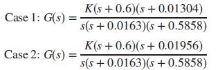
b. In most cases, perfect pole-zero cancellation is not possible. Assume that you want to check what happens if the PI-controller’s zero changes by ± 20%, e.g., if ZI moves to:
Case 1: - 0:01304
or to
Case 2: - 0:01956.
The plant and controller transfer function in these cases will be, respectively:
Set K in each case to the value required by the steady-state error specifications and plot the Bode magnitude and phase diagrams. Simulate the closed loop step response for each of the three locations of ZI: pole/zero cancellation, Case 1, and Case 2, given in the problem.
Do the responses obtained resemble a second order overdamped, critically damped, or underdamped response? Is there a need to add a derivative mode?
Step by Step Answer:

This question has not been answered yet.
You can Ask your question!