Problem 8 in Chapter 1 describes a high-speed proportional solenoid valve. A subsystem of the valve is
Question:
Problem 8 in Chapter 1 describes a high-speed proportional solenoid valve. A subsystem of the valve is the solenoid coil shown in Figure P5.32. Current through the coil, L, generates a magnetic field that produces a force to operate the valve. Figure P5.32 can be represented as a block diagram (Vaughan, 1996).
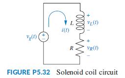
a. Derive a block diagram of a feedback system that represents the coil circuit, where the applied voltage, vg(t), is the input, the coil voltage, vL(t), is the error voltage, and the current, i(t), is the output.
b. For the block diagram found in Part a, find the Laplace transform of the output current, I(s).
c. Solve the circuit of Figure P5.32 for I(s), and compare to your result in Part b.
Data From Problem 8
You are given a high-speed proportional solenoid valve. A voltage proportional to the desired position of the spool is applied to the coil. The resulting magnetic field produced by the current in the coil causes the armature to move. A push pin connected to the armature moves the spool. A linear voltage differential transformer (LVDT) that outputs a voltage proportional to displacement senses the spool’s position. This voltage can be used in a feedback path to implement closed-loop operation (Vaughan, 1996). Draw a functional block diagram of the valve, showing input and output positions, coil voltage, coil current, and spool force.
Step by Step Answer:

This question has not been answered yet.
You can Ask your question!