

Question: Repeat Problem47 using a lag-lead compensator instead of a PID controller. Design for a steady-state error of 1% for a step input command. Data From
Repeat Problem47 using a lag-lead compensator instead of a PID controller. Design for a steady-state error of 1% for a step input command.
Data From Problem 47:
Steam-driven power generators rotate at a constant speed via a governor that maintains constant steam pressure in the turbine. In addition, automatic generation control (AGC) or load frequency control (LFC) is added to ensure reliability and consistency despite load variations or other disturbances that can affect the distribution line frequency output. A specific turbine-governor system can be described only using the block diagram of Figure P9.1 in which G(s) = Gc(s)Gg(s)Gt(s)Gm(s), where (Khodabakhshian, 2005)
a. Assuming Gc(s) = K, find the value of K that will result in a dominant pole with ζ = 0.7. Obtain the corresponding Ts.
b. Design a PID controller to obtain the same damping factor as in Part a, but with a settling time of 2 seconds and zero steady-state error to step input commands.
c. Verify your results using a MATLAB simuation.
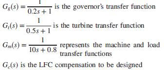
G(s) = is the governor's transfer function 0.2s + 1 G,(s) = is the turbine transfer function 0.5s + 1 1 10s + 0.8 represents the machine and load transfer functions Gm(s) = G(8) is the LFC compensation to be designed
Step by Step Solution
3.44 Rating (157 Votes )
There are 3 Steps involved in it

Get step-by-step solutions from verified subject matter experts