

Consider the robot joint control system of Problem 5.3-13 and Fig. P5.3-13. Let D (z) = 1
Question:
Consider the robot joint control system of Problem 5.3-13 and Fig. P5.3-13. Let D(z) = 1 ,T = 0.1 s, and K = 2.4 .
(a) Using the closed-loop transfer function, derive a discrete state model for the system.
(b) Derive a discrete state model for the plant from the plant transfer function. Then derive a state model for the closed-loop system by adding the feedback path and system input to a flow graph of the plant.
(c) Calculate the system transfer function from the state model found in part (b), to verify the state
model.
Problem 5.3-13
Consider the robot-joint control system of Fig. P5.3-13. This system is described in Problem 1.5-4.
(a) The sensor input is θa in degrees and the output is in volts. If the robot joint movement is mechanically restricted to ±135°, find the range of the sensor output voltage. What should be the input voltage range for the A/D?
(b) Let Gp(s) be the transfer function of the servomotor and gears, and Hk = 0.05 be the sensor gain. Find the system transfer function as a function of K, Gp(s), and so on.
(c) Evaluate the system transfer function for K = 1.4, T = 0.3 s, and D(z) = 1.1.
Fig. P5.3-13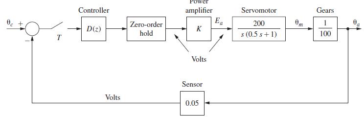
Step by Step Answer:
a From Problem 5313 xk1 a Yz U 2 0 08216 18156 yk004488 004206xk uk 24 b F...View the full answer


Digital Control System Analysis And Design
ISBN: 9780132938310
4th Edition
Authors: Charles Phillips, H. Nagle, Aranya Chakrabortty
