

Consider the temperature control system of Problem 5.3-12 and Fig. P5.3-12. Suppose that the digital filter transfer
Question:
Consider the temperature control system of Problem 5.3-12 and Fig. P5.3-12. Suppose that the digital filter transfer function is given by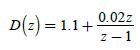
which is a PI (proportional-integral) controller. Suppose that T = 0.6 s , and let Rd(s) = 0 (ignore the disturbance input).
(a) Using the closed-loop transfer function, derive a discrete state model for the system.
(b) Derive a discrete state model for the plant from the plant transfer function. Then derive the state model of the closed-loop system by adding the filter and the feedback path to the flow graph of the plant.
(c) Calculate the transfer function from the state model of part (b), to verify these results.
(d) How are the states of parts (a) and (b) related? Do not solve for the exact relationship.
Problem 5.3-12
Shown in Fig. P5.3-12 is the block diagram for the temperature control system for a large test chamber.
This system is described in Problem 1.6-1. The disturbance shown is the model of the effects of opening the
chamber door. The following transfer functions are defined.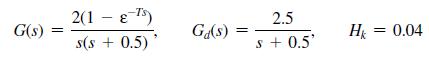
(a) Derive the transfer function C(z)>R(z), in terms of the transfer functions just defined.
(b) With r(t) = 0, solve for the output function C(s) in terms of the disturbance input and the transfer functions just defined.
(c) Use superposition and the results of parts (a) and (b) to write the complete expression of C(z).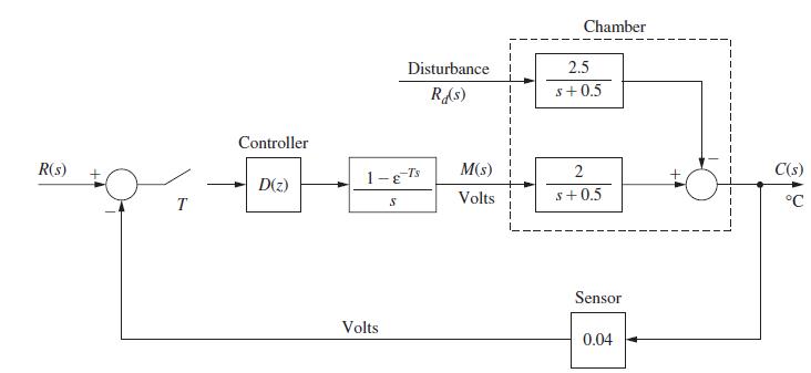
Step by Step Answer:
b 02z 112z11 21 z1 Dz 11 a From Problem 461 Gz DzGz 1 DzG2H xk1 11614z 1140 z 16943z 07001 1037 ...View the full answer


Digital Control System Analysis And Design
ISBN: 9780132938310
4th Edition
Authors: Charles Phillips, H. Nagle, Aranya Chakrabortty
