

For the temperature control system of Problem 7.5-3 and Fig. P7.5-3, let K = 1 . (a)
Question:
For the temperature control system of Problem 7.5-3 and Fig. P7.5-3, let K = 1 .
(a) Determine the stability of the system.
(b) Plot the Bode diagram, and the Nyquist diagram.
(c) If the system is stable, determine the gain and phase margins. If the system is unstable, find the value of K that gives a phase margin of 45° .
(d) From the Nyquist diagram, determine the value of K >0 for which the system is marginally stable.
(e) Find the frequency ω at which the marginally stable system will oscillate.
Problem 7.5-3
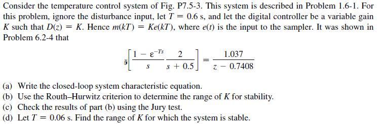

Problem 1.6-1
A thermal test chamber is illustrated in Fig. P1.6-1(a). This chamber, which is a large room, is used to test
large devices under various thermal stresses. The chamber is heated with steam, which is controlled by an
electrically activated valve. The temperature of the chamber is measured by a sensor based on a thermistor,
which is a semiconductor resistor whose resistance varies with temperature. Opening the door into the
chamber affects the chamber temperature and thus must be considered as a disturbance.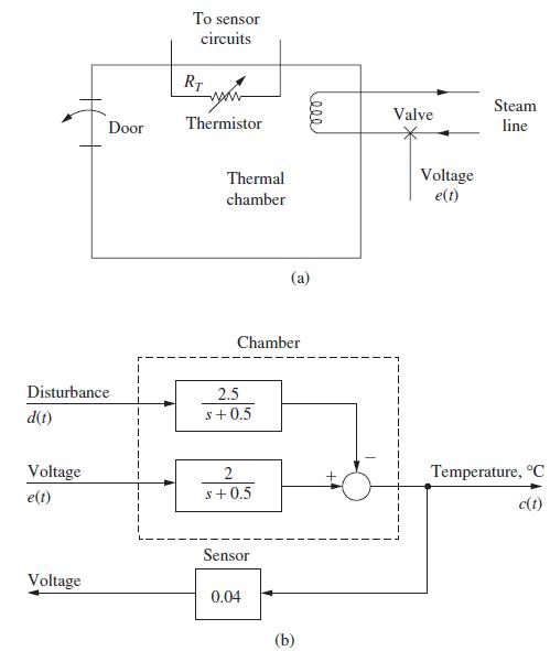
Step by Step Answer:
a From Problem 753 stable for K 1 b From Problem 762 ...View the full answer


Digital Control System Analysis And Design
ISBN: 9780132938310
4th Edition
Authors: Charles Phillips, H. Nagle, Aranya Chakrabortty
