

Shown in Fig. P6.2-4 is the block diagram of a temperature control system for a large test
Question:
Shown in Fig. P6.2-4 is the block diagram of a temperature control system for a large test chamber. This system is described in Problem 1.6-1. Ignore the disturbance input for this problem.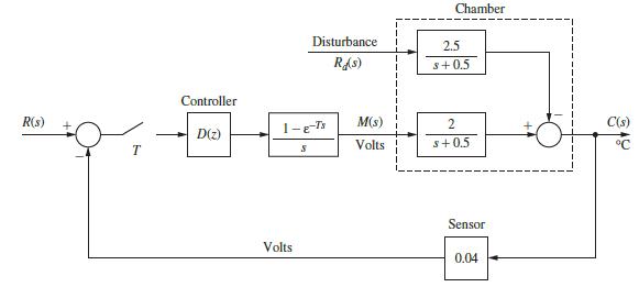
(a) With D(z) = 1 and T = 0.6 s , evaluate and plot the system response if the input is to command a 10°C step in the output. Note that the system input must be a step function with an amplitude of 0.4 V. Why?
(b) Use the results of part (a) to plot the output of the zero-order hold.
(c) Solve for the steady-state output for part (a).
(d) Suppose that the gain of 2 in the plant is replaced with a variable gain K. What value does the output approach in the steady state as K becomes very large? Assume that the system remains stable as K is increased (an unrealistic assumption).
Problem 1.6-1
A thermal test chamber is illustrated in Fig. P1.6-1(a). This chamber, which is a large room, is used to test large devices under various thermal stresses. The chamber is heated with steam, which is controlled by an electrically activated valve. The temperature of the chamber is measured by a sensor based on a thermistor, which is a semiconductor resistor whose resistance varies with temperature. Opening the door into the chamber affects the chamber temperature and thus must be considered as a disturbance.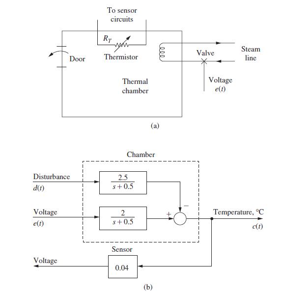
Step by Step Answer:
a From Problem 421 Gz Gz 1037 1G2H Z07408 1037004 Z0...View the full answer


Digital Control System Analysis And Design
ISBN: 9780132938310
4th Edition
Authors: Charles Phillips, H. Nagle, Aranya Chakrabortty
