

The system of Example 7.1 and Fig. 7-3 has two samplers. The system characteristic equation is derived
Question:
The system of Example 7.1 and Fig. 7-3 has two samplers. The system characteristic equation is derived in Example 7.1 as![]()
Show that the same characteristic equation is obtained by opening the system at the second sampler.
Example 7.1
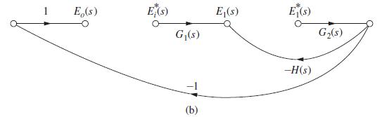
Consider the system of Example 5.2, which is repeated in Fig. 7-3(a). The flow graph of the system is opened at the first sampler as shown in Fig. 7-3(b). The effect of the second sampler is included, by denoting its input as E1(s) and its output as E*1 (s). From this flow graph we write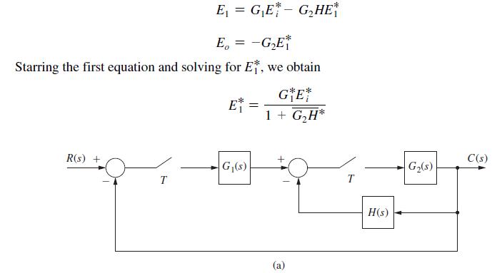
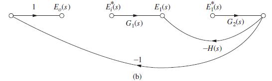
Fig 7-3(a), (b)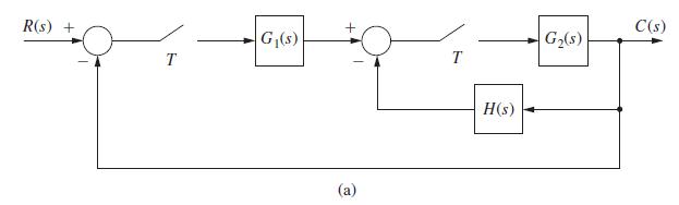
Example 7.2
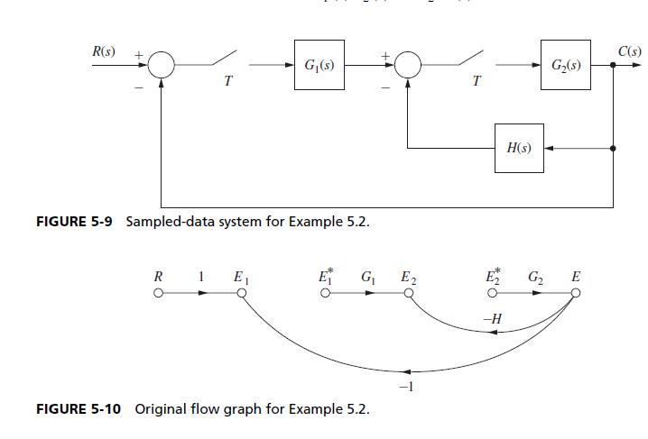
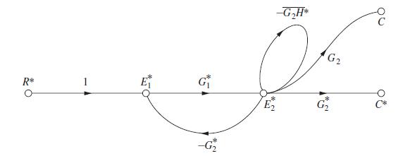
Consider the system shown in Fig. 5-9. The original signal flow graph is shown in Fig. 5-10.
The system equations are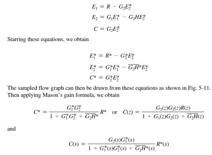
Step by Step Answer:
A A G 1 E 1G G G...View the full answer


Digital Control System Analysis And Design
ISBN: 9780132938310
4th Edition
Authors: Charles Phillips, H. Nagle, Aranya Chakrabortty
