

Question: Two systems, A and B, use the encoding of Table 1.1 to send logic signals to one another. Suppose there is a voltage shift between
Two systems, A and B, use the encoding of Table 1.1 to send logic signals to one another. Suppose there is a voltage shift between the two systems’ power supplies so that all voltages in A are VN higher than in B. A voltage of Vx in system A appears as a voltage of Vx + VN in system B. A voltage of Vx in system B appears as a voltage of Vx − VN in system A. Assuming that there are no other noise sources, over what range of VN will the system operate properly?
Data in Table 1.1
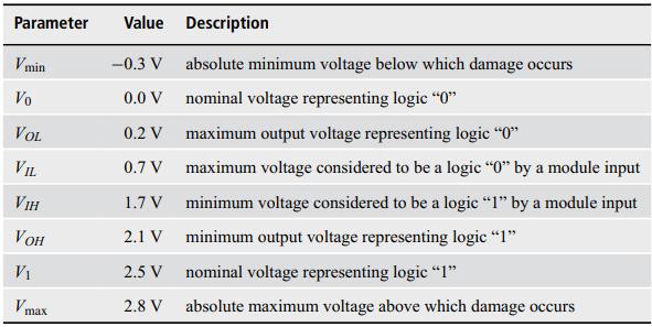
Parameter V min Vo VOL VIL VIH VOH V Vmax Value -0.3 V 0.0 V 0.2 V 0.7 V 1.7 V 2.1 V 2.5 V 2.8 V Description absolute minimum voltage below which damage occurs nominal voltage representing logic "0" maximum output voltage representing logic "0" maximum voltage considered to be a logic "0" by a module input minimum voltage considered to be a logic "1" by a module input minimum output voltage representing logic "1" nominal voltage representing logic "1" absolute maximum voltage above which damage occurs
Step by Step Solution
3.46 Rating (169 Votes )
There are 3 Steps involved in it
V... View full answer

Get step-by-step solutions from verified subject matter experts