

Question: Realize the following next-state equation using a minimum number of Figure 6-1(a) logic blocks. Draw a diagram that shows the connections to the logic blocks
Realize the following next-state equation using a minimum number of Figure 6-1(a) logic blocks. Draw a diagram that shows the connections to the logic blocks and give the functions X and Y for each cell. (The equation is already in minimum form.)
Q+ = UQV'W + U'Q'VX'Y' + UQX'Y + U'Q'V'Y + U'Q'XY + UQVW' + U'Q'V'X
Figure 6-1(a)
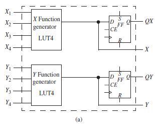
X X Function QX D FF CE X2 generator X - LUT4 X4- Y - Y Function generator to Y2 - D FF QY CE Y3 LUT4 YA Y L (a) L.
Step by Step Solution
3.39 Rating (155 Votes )
There are 3 Steps involved in it
Expanding Q around U Q results in 4 variable equations which can be realized using one f... View full answer

Get step-by-step solutions from verified subject matter experts