

Question: Compare the operation of two counters, one with synchronous load and the other with asynchronous load. Refer to Figure 7-18(a), in which a 74ALS163 and
Compare the operation of two counters, one with synchronous load and the other with asynchronous load. Refer to Figure 7-18(a), in which a 74ALS163 and a 74ALS191 have been wired in a similar fashion to count up in binary. Both chips are driven by the same clock signal and have their QD and QC outputs NANDed together to control the respective L̅O̅A̅D̅ input control. Assume that both counters are initially in the 0000 state.
(a) Determine the output waveform for each counter.
(b) What is the recycling count sequence and modulus for each counter?
(c) Why do they have different count sequences?
(d) Draw the complete (include all 16 states) state transition diagram for each counter.
Figure 7-18(a)
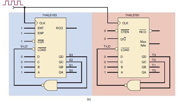
n 1 1 1 S-LD 0 0 0 1 74ALS163 CLK ENT ENP CLR LOAD D B A RCO QD QC QB QA S3 S2 S1 SO (a) O 0 T-LD 0 OOOT 0 0 1 CLK CTEN DV 74ALS191 LOAD DCBA RCO Max /Min QD QC QB QA T3 T2 T1 TO
Step by Step Solution
3.47 Rating (160 Votes )
There are 3 Steps involved in it
a Starting at state 0000 each counter will count up until it reaches state 1100 12 as shown in Figur... View full answer

Get step-by-step solutions from verified subject matter experts