

Question: Refer to Figure 3-40 in Example 3-23. Inputs A 7 through A 0 are address inputs that are supplied to this circuit from outputs of
Refer to Figure 3-40 in Example 3-23. Inputs A7 through A0 are address inputs that are supplied to this circuit from outputs of the microprocessor chip in a microcomputer. The eight-bit address code A7 to A0 selects which device the microprocessor wants to activate. In Example 3-23, the required address code to activate the LCD was A7 through A0 = 111111102 = FE16.
Modify the circuit so that the microprocessor must supply an address code of 4A16 to activate the LCD.
Data from Example 3-23
The logic circuit in Figure 3-40 is used to enable the liquid crystal display (LCD) of a handheld electronic device when the microcontroller is sending data to or receiving data from the LCD controller. The circuit will enable the display when LCD = 1. Determine the input conditions necessary to enable the LCD.
Figure 3-40
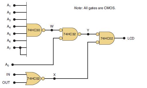
A A A3 A4 A5 As A7 A IN OUT 74HC30 74HC02 W X Note: All gates are CMOS. 74HC32 74HC02 LCD
Step by Step Solution
3.37 Rating (153 Votes )
There are 3 Steps involved in it

Get step-by-step solutions from verified subject matter experts