

Refer to the binary counter of Figure 5-48. Change it by connecting X 0 to the CLK
Question:
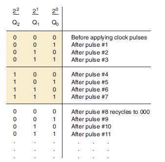
Refer to the binary counter of Figure 5-48. Change it by connecting X̅0 to the CLK of flip-flop X1, and X̅1 to the CLK of flip-flop X2. Start with all FFs in the 1 state, and draw the various FF output waveforms (X0, X1, X2,) for 16 input pulses. Then list the sequence of FF states as was done in Figure 5-49. This counter is called a down counter. Why?
Figure 5-48
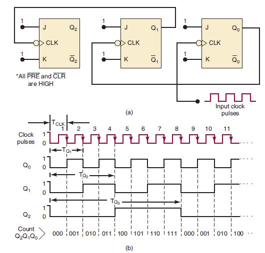
Figure 5-49
Step by Step Answer:

This question has not been answered yet.
You can Ask your question!
Related Book For 

Digital Systems Principles And Application
ISBN: 9780134220130
12th Edition
Authors: Ronald Tocci, Neal Widmer, Gregory Moss
Question Posted:
