

The circuit in Figure 5-100 can be used to generate two nonoverlapping clock signals at the same
Question:
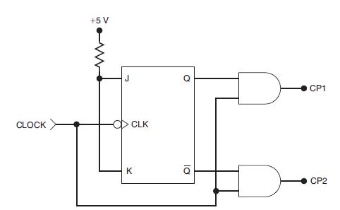
The circuit in Figure 5-100 can be used to generate two nonoverlapping clock signals at the same frequency. These clock signals were used in early microprocessor systems that required four different clock transitions to synchronize their operations.
(a) Draw the CP1 and CP2 timing waveforms if CLOCK is a 1-MHz square wave. Assume that tPLH and tPHL are 20 ns for the FF and 10 ns for the AND gates.
(b) This circuit would have a problem if the FF were changed to one that responds to a PGT at CLK. Draw the CP1 and CP2 waveforms for that situation. Pay particular attention to conditions that can produce glitches.
Figure 5-100
Step by Step Answer:

This question has not been answered yet.
You can Ask your question!
Related Book For 

Digital Systems Principles And Application
ISBN: 9780134220130
12th Edition
Authors: Ronald Tocci, Neal Widmer, Gregory Moss
Question Posted:
