

Question: Numerically generate and plot the fields of stress ( r , ) and displacement (u r ) within the composite cylinder of Exercise
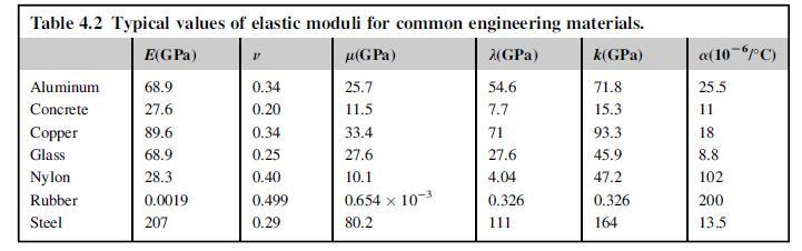
Numerically generate and plot the fields of stress (σr, σθ) and displacement (ur) within the composite cylinder of Exercise 8.20 for the specific case with material (1) = steel and material (2) = aluminum. Use Table 4.2 for elastic moduli values. Explore and discuss the continuity issues for these field quantities at the interface r = r1.
Table 4.2
Data from exercise 8.20
A long composite cylinder is subjected to the external pressure loading as shown in the following figure. Assuming idealized perfect bonding between the two materials, the normal stress and displacement will be continuous across the interface r = r1 (see Section 5.2). Under these conditions, determine the stress and displacement fields in each material.
![Material (1) 11 t I-N ----- lllllm A--- lalala [11] illal. 2011 |-|-|-17 (2 (sl lyr TI-TY Material (2)](https://dsd5zvtm8ll6.cloudfront.net/images/question_images/1706/2/0/7/26265b2a81e938a31706207261976.jpg)
Table 4.2 Typical values of elastic moduli for common engineering materials. (GPa) (GPa) k(GPa) Aluminum Concrete Copper Glass Nylon Rubber Steel E(GPa) 68.9 27.6 89.6 68.9 28.3 0.0019 207 P 0.34 0.20 0.34 0.25 0.40 0.499 0.29 25.7 11.5 33.4 27.6 10.1 0.654 x 10⁻³ 80.2 54.6 7.7 71 27.6 4.04 0.326 111 71.8 15.3 93.3 45.9 47.2 0.326 164 a(10-6PC) 25.5 11 18 8.8 102 200 13.5
Step by Step Solution
3.46 Rating (156 Votes )
There are 3 Steps involved in it
Solutions from Exercise 820 Material 10 B Material 2 2 u2 1 1 ... View full answer

Get step-by-step solutions from verified subject matter experts