

A simplified schematic drawing of the carburetor of a gasoline ((S=0.75)) engine is shown in Fig. P5.96.
Question:
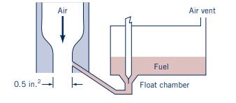
A simplified schematic drawing of the carburetor of a gasoline \((S=0.75)\) engine is shown in Fig. P5.96. The throat area is \(0.5 \mathrm{in.}^{2}\). The running engine draws air downward through the carburetor Venturi and maintains a throat pressure of 14.3 psia. The low throat pressure draws fuel from the float chamber and into the airstream. The energy losses in the 0.07-in.-diameter fuel metering line and valve are given by
\[ g h_{L}=\frac{K V^{2}}{2 g} \]
where \(\mathrm{K}=6.0\) and \(V\) is the fuel velocity in the metering line. Assume that the air is an ideal fluid having a constant density \(ho_{A}\) \(=0.075 \mathrm{lbm} / \mathrm{ft}^{3}\). The atmospheric pressure is \(14.7 \mathrm{psia}\). Calculate the air-to-fuel ratio \(\left(\dot{m}_{\mathrm{a}} / \dot{m}_{\mathrm{f}}\right)\).
Figure P5.96
Step by Step Answer:


Munson Young And Okiishi's Fundamentals Of Fluid Mechanics
ISBN: 9781119080701
8th Edition
Authors: Philip M. Gerhart, Andrew L. Gerhart, John I. Hochstein
