New Semester
Started
Get
50% OFF
Study Help!
--h --m --s
Claim Now
Question Answers
Textbooks
Find textbooks, questions and answers
Oops, something went wrong!
Change your search query and then try again
S
Books
FREE
Study Help
Expert Questions
Accounting
General Management
Mathematics
Finance
Organizational Behaviour
Law
Physics
Operating System
Management Leadership
Sociology
Programming
Marketing
Database
Computer Network
Economics
Textbooks Solutions
Accounting
Managerial Accounting
Management Leadership
Cost Accounting
Statistics
Business Law
Corporate Finance
Finance
Economics
Auditing
Tutors
Online Tutors
Find a Tutor
Hire a Tutor
Become a Tutor
AI Tutor
AI Study Planner
NEW
Sell Books
Search
Search
Sign In
Register
study help
engineering
principles of composite
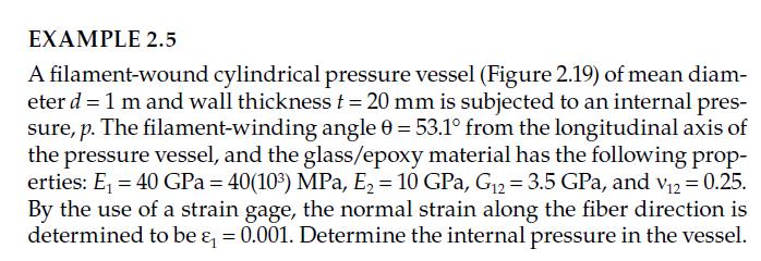
Principles Of Composite Material Mechanics 4th Edition Ronald F. Gibson - Solutions
Describe an experiment, and give the necessary equations for the measurement of the complex extensional (or longitudinal) modulus, \(E_{x}^{*}\), of a symmetric laminated bar.
Describe an experiment, and give the necessary equations for the measurement of the complex through-thickness shear modulus, \(G_{23}^{*}\), of a unidirectional, specially orthotropic, transversely isotropic beam.
Describe an experiment, and give the necessary equations for measurement of the complex Young's modulus, \(E_{\mathrm{m}}^{*}\), of an isotropic matrix material.
Describe an experiment, and give the necessary equations for the measurement of the complex longitudinal modulus, \(E_{\mathrm{f} 1}^{*}\), of a reinforcing fiber.
Describe an experiment, and give the necessary equations for measurement of the through-thickness creep compliance, \(S_{32}(t)\), of a specially orthotropic, transversely isotropic lamina. The plate from which the test specimen is to be cut lies in the 12 plane with fibers oriented parallel to the
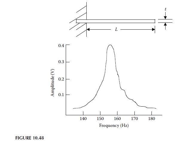
The specimen geometry and the frequency response curve for the second mode flexural vibration of a laminated composite cantilever beam specimen is shown in Figure 10.48. The specimen has length \(L=8.913\) in., width \(w=0.756 \mathrm{in}\)., thickness \(t=0.04 \mathrm{in}\)., and specific weight
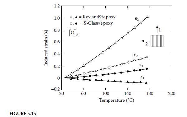
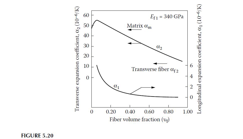
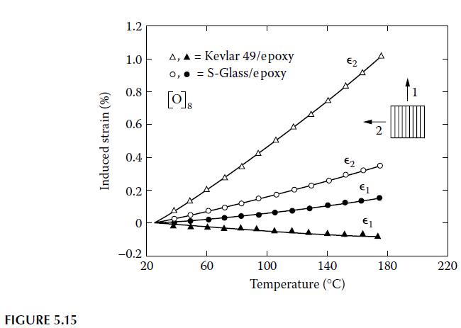
Samples of unidirectional Kevlar 49/epoxy and S-glass/epoxy composites are subjected to elevated temperatures in an oven and the resulting thermal strains are measured by using strain gages oriented along the 1 and 2 directions, as shown in Figure 5.15. From the data in Figure 5.15, estimate the
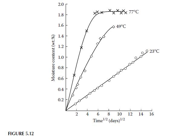
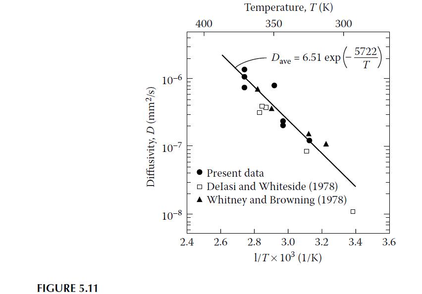
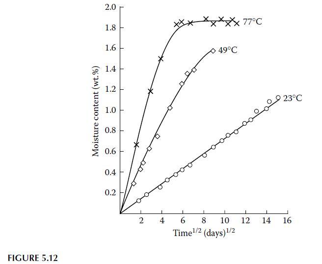
For the linear part of the moisture absorption curve for a temperature of \(77^{\circ} \mathrm{C}\) in Figure 5.12, and assuming a specimen thickness of \(2.54 \mathrm{~mm}\), use the relevant analysis from ASTM D5229 to estimate the through-the-thickness diffusivity \(D_{z}\). FIGURE 5.12 Moisture
Repeat Example 5.1 for the cases where the hygrothermal conditions change from (a) RT dry to \(300^{\circ} \mathrm{F} \mathrm{dry}\), and (b) from RT dry to RT wet, then compare with the results from Example 5.1. That is, compare the effect of combined elevated temperature and moisture (Example
Using Equation 5.6 for moisture diffusion, derive an equation for the time required for an initially dry material to reach \(99.9 \%\) of its fully saturated equilibrium moisture content. The series in Equation 5.6 converges rapidly, so for the purposes of this problem, it is necessary only to
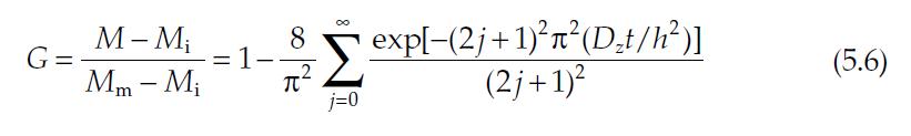
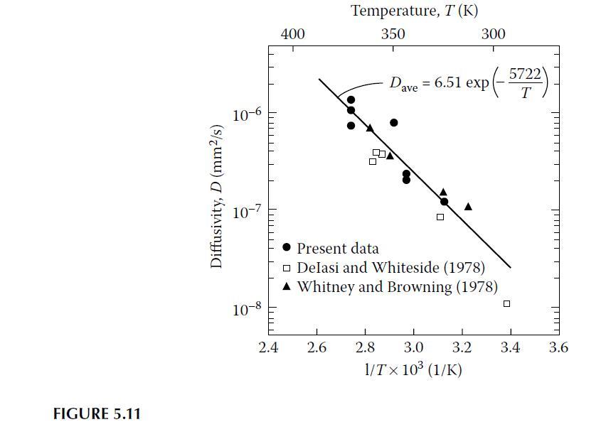
The dependence of the transverse (through-the-thickness) diffusivity of unidirectional AS/3501-5 graphite/epoxy composite on temperature is given in Figure 5.11. For a temperature of \(77^{\circ} \mathrm{C}\) and a thickness of \(2.54 \mathrm{~mm}\), use the results from Figure 5.11 and Problem 5.2
For the material described in Problems 5.2 and 5.3 above at a temperature of \(77^{\circ} \mathrm{C}\), determine the time required for drying the material from \(99.9 \%\) to \(50 \%\) of its fully saturated equilibrium moisture content.Problem 5.3The dependence of the transverse
Using only the linear part of the moisture absorption curve for a temperature of \(77^{\circ} \mathrm{C}\) in Figure 5.12, and assuming a thickness of \(2.54 \mathrm{~mm}\), estimate the diffusivity \(D_{z}\). Compare this value with the estimate from Figure 5.11. FIGURE 5.11 Diffusivity, D (mm2/s)
For the composite properties and environmental conditions described in Examples 3.6, 4.7, and 5.3, determine the hygrothermally degraded values of the longitudinal and transverse tensile strengths. Compare with the reference values of these strengths from Example 4.7.
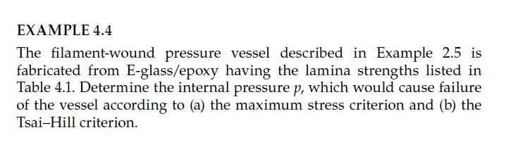
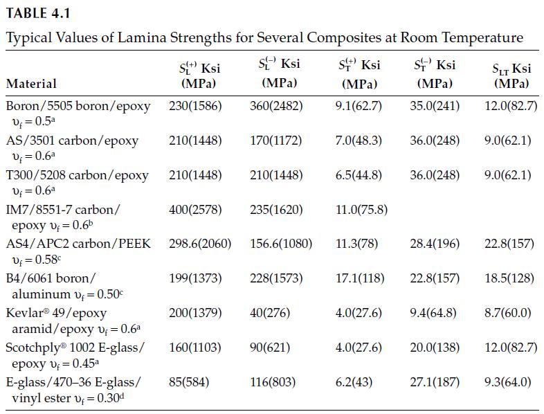
The filament-wound E-glass/epoxy pressure vessel described in Example 4.4 is to be used in a hot-wet environment with temperature \(T=100^{\circ} \mathrm{F}\) \(\left(38^{\circ} \mathrm{C}\right)\) and moisture content \(M_{r}=4 \%\). The glass transition temperature of the dry epoxy resin is
An orthotropic lamina forms one layer of a laminate which is initially at temperature \(T_{0}\). Assuming that the lamina is initially stress free, that the adjacent laminae are rigid, that the properties do not change as a result of the temperature change, and that the lamina picks up no moisture,
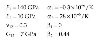
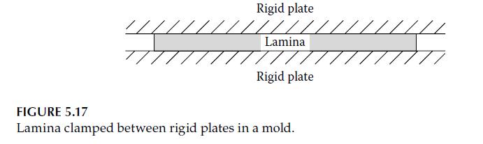
A carbon/epoxy lamina is clamped between rigid plates in a mold (Figure 5.17), while curing at a temperature of \(125^{\circ} \mathrm{C}\). After curing, the lamina/mold assembly (still clamped together) is cooled from \(125^{\circ} \mathrm{C}\) to \(25^{\circ} \mathrm{C}\). The cooling process
Samples of unidirectional Kevlar 49/epoxy and S-glass/epoxy composites are subjected to elevated temperatures in an oven and the resulting thermal strains are measured by using strain gages oriented along the 1 and 2 directions, as shown in Figure 5.15. From the data in Figure 5.15, estimate the
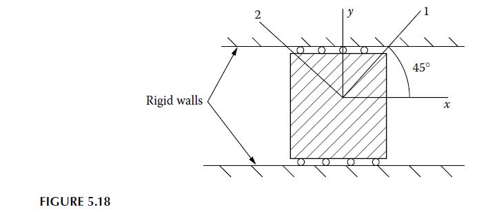
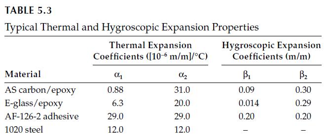
A unidirectional \(45^{\circ}\) off-axis E-glass/epoxy composite lamina is supported on frictionless rollers between rigid walls as shown in Figure 5.18. The lamina is fixed against displacements in the \(y\)-direction, but is free to move in the \(x\)-direction. Determine all of the lamina strains
An orthotropic lamina has thermal expansion coefficients \(\alpha_{1}=-4.0\) \(\left(10^{-6}\right) \mathrm{m} / \mathrm{m} / \mathrm{K}\) and \(\alpha_{2}=79\left(10^{-6}\right) \mathrm{m} / \mathrm{m} / \mathrm{K}\). Determine (a) the angle \(\theta\) for which the thermal expansion coefficient
A carbon/epoxy lamina having the properties listed in Problem 5.10 is clamped between two rigid plates as shown in Figure 5.17. If the lamina is heated from \(20^{\circ} \mathrm{C}\) to \(120^{\circ} \mathrm{C}\), determine the thermal stresses associated with the principal material axes of the
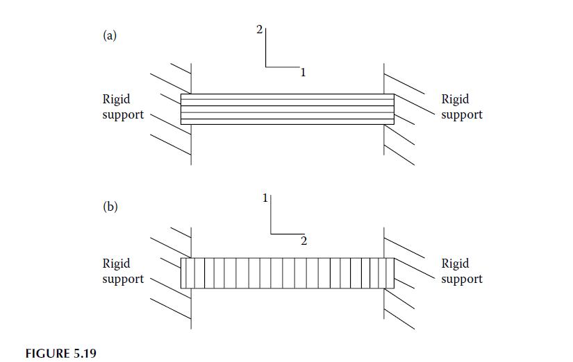
A unidirectional E-glass/epoxy lamina is securely attached to rigid supports on both ends in two different ways as shown in Figure 5.19. In Figure 5.19a, the fiber direction is perpendicular to the rigid supports, and in Figure 5.19b, the fibers are oriented parallel to the rigid supports. The
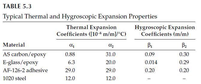
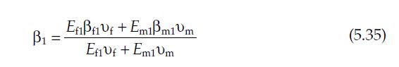
Derive Equation 5.35. 1 = Efiff +Emim1vm Ef1 Vf+ Em1Vm (5.35)
Develop an analytical model for determination of the CTE, \(\alpha\), for a randomly oriented continuous fiber composite in terms of fiber and matrix properties and volume fractions. Assume that the composite is planar isotropic and find the \(\alpha\) for in-plane thermal expansion.
A unidirectional graphite/epoxy lamina having the properties described in Problem 5.10 is to be designed to have a CTE of zero along a particular axis. Determine the required lamina orientation for such a design.Problem 5.10A carbon/epoxy lamina is clamped between rigid plates in a mold (Figure
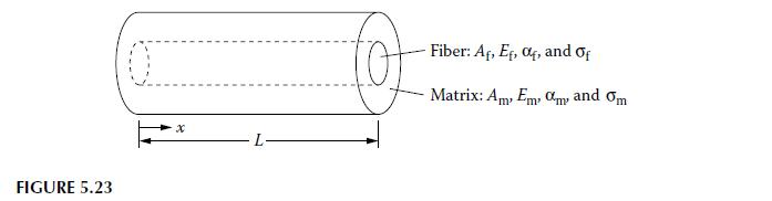
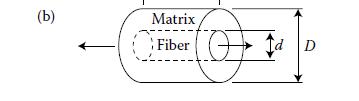
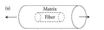
A representative volume element (RVE) consisting of a cylindrical isotropic fiber embedded and perfectly bonded in a cylinder of isotropic matrix material is shown in Figure 5.23. If the ends of the RVE at \(x=0\) and \(x=L\) and the outer surface of the RVE are stress free and the RVE is subjected
Derive Equations 5.26 and 5.30 . == Ef10f1Vf+ Em1m1Vm_ Ef1ff + Em1m1vm 1 Ef1Vf+ Em1Vm (5.26)
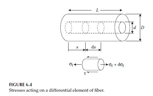
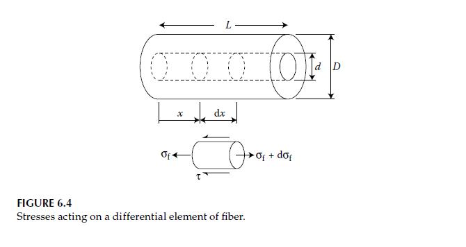
The interfacial shear stresses, \(\tau\), and the fiber normal stresses, \(\sigma_{f}\) acting on a differential element at a distance \(x\) from the end of the fiber are shown in Figure 6.4, where the fiber is assumed to have a circular cross section of diameter \(d\). In some cases, fibers may
A short-fiber composite is to be modeled using the RVE in Figure 6.2b. Assuming that the matrix is rigid plastic in shear but that both the fiber and matrix are elastic in extension, develop an equation for the longitudinal modulus of the RVE. What values of the longitudinal modulus does the model
Using the result from Problem 6.2, develop an expression for the longitudinal modulus of the RVE shown in Figure 6.2a that includes the effect of the matrix material at the fiber ends.Problem 6.2A short-fiber composite is to be modeled using the RVE in Figure 6.2b. Assuming that the matrix is rigid
A carbon/epoxy single fiber test specimen is subjected to a uniaxial tensile stress that is increased until the fiber breaks up into pieces having a length of \(0.625 \mathrm{~mm}\). If the fiber has a diameter of \(0.01 \mathrm{~mm}\), a longitudinal modulus of \(240 \mathrm{GPa}\), and an
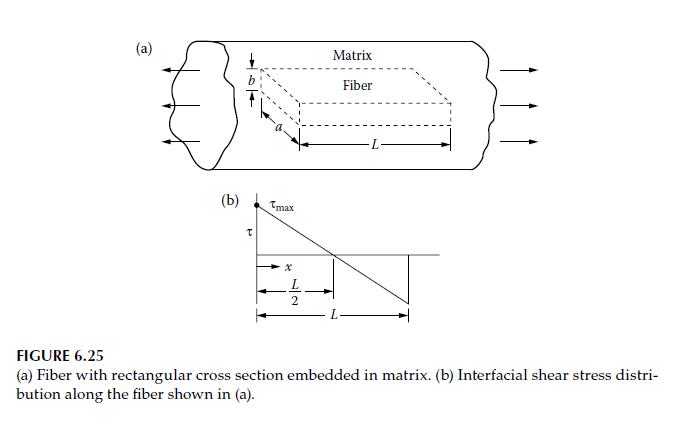
A linear elastic fiber of rectangular cross section is embedded in a linear elastic matrix material, and the composite is subjected to a uniaxial stress as shown in Figure 6.25a. The interfacial shear stress distribution along the fiber is to be approximated by a linear function, as shown in Figure
The RVE for an aligned discontinuous fiber composite without matrix material at its ends is shown in Figure 6.4. Assume that when the RVE is loaded along the fiber direction, the interfacial shear stress distribution is given by\[\tau=\frac{2 \tau_{\max }}{L}\left(\frac{L}{2}-x\right)\]and the
For the RVE in Figure 6.4, assume that the fiber length is greater than the ineffective length, and that the distribution of the fiber tensile normal stress is given by\[\begin{gathered} \sigma_{\mathrm{f}}=\frac{4 \sigma_{\mathrm{fmax}} x\left(L_{\mathrm{i}}-x\right)}{L_{\mathrm{i}}^{2}} \text {
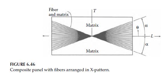
In order to reduce material costs, a composite panel is to be made by placing fibers in the matrix material in an X-pattern of \(\pm \alpha\) as shown in Figure 6.46, instead of randomly distributing the fibers over all angles. The X-pattern composite is to be designed so that it has at least \(90
Determine the CTE for a randomly oriented fiber composite in terms of the longitudinal and transverse CTEs \(\alpha_{1}\) and \(\alpha_{2}\) of the corresponding unidirectional composite lamina.
Using micromechanics and the Tsai-Hill criterion, set up the equation for the averaged isotropic tensile strength for a randomly oriented short-fiber composite. The equation should be in terms of fiber and matrix properties and volume fractions and the angle \(\theta\).
Set up the equations for predicting the averaged isotropic shear modulus of a randomly oriented short-fiber composite. Your answer should be in terms of the fiber and matrix properties and volume fractions and trigonometric functions of the fiber orientation angle, \(\theta\). It is not necessary
Using the Tsai-Hill criterion and the appropriate micromechanics equations, set up the equation for predicting the averaged isotropic shear strength for a randomly oriented short-fiber composite. Your answer should be in terms of the fiber and matrix properties and volume fractions and
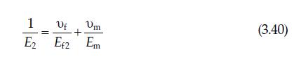
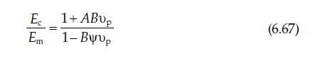
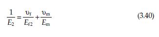
Verify the three predictions (i.e., Equations 3.27, 3.40, and 6.67) for the Young's modulus of the glass microsphere-reinforced polyester composite in Figure 6.42 for the specific case of a particle volume fraction of 0.464 . The required input data are given in the text accompanying the discussion
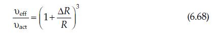
Derive Equation 6.68. Veff 1+ Dact AR -(1.4) (6.68) R
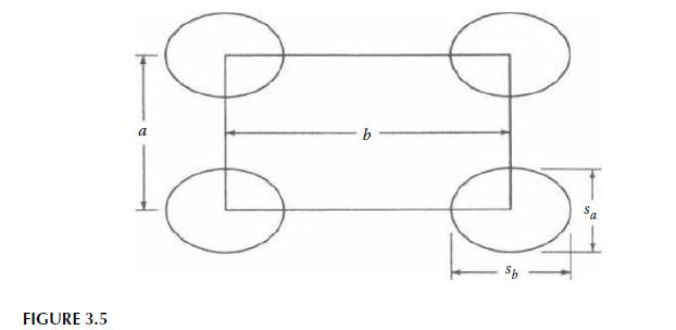
A rectangular array of elliptical fibers is shown in Figure 3.5. Derive the relationship between the fiber volume fraction and the given geometrical parameters. What is the maximum possible fiber volume fraction for this packing geometry? FIGURE 3.5 a Sb
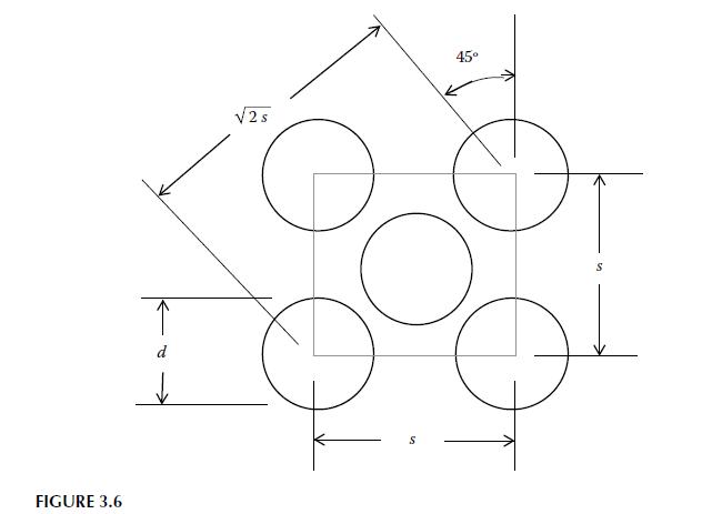
A face-centered cubic array of round fibers is shown in Figure 3.6. Derive the relationship between the fiber volume fraction and the given geometrical parameters. What is the maximum possible fiber volume fraction for this fiber-packing geometry? FIGURE 3.6 d 2s 45
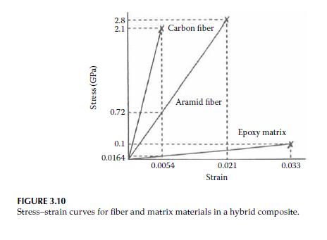
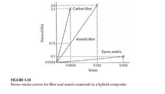
A hybrid carbon-aramid/epoxy composite is made by randomly mixing continuous aligned fibers of the same diameter, so that there are two carbon fibers for each aramid fiber. The fibers are assumed to be arranged in a square array with the closest possible packing. The stress-strain curves for
Derive Equation 3.45. V12 = V12Vf+ VmVm (3.45)
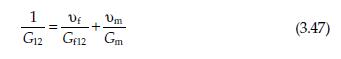
Derive Equation 3.47. 1 Um +. (3.47) G12 Gf12 Gm
Using an elementary mechanics of materials approach, find the micromechanics equation for predicting the minor Poisson's ratio, \(v_{21}\), for a unidirectional fiber composite in terms of the corresponding fiber and matrix properties and volume fractions. Assume that the fibers are orthotropic,
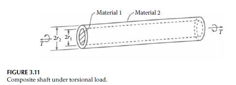
A composite shaft is fabricated by bonding an isotropic solid shaft having shear modulus \(G_{1}\), and outside radius \(r_{1}\), inside a hollow isotropic shaft having shear modulus \(G_{2}\) and outside radius \(r_{2}\). The composite shaft is to be loaded by a twisting moment, \(T\), that is
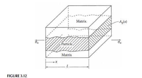
An RVE from a particle-reinforced composite is shown in Figure 3.12. The particle has a cross-sectional area \(A_{\mathrm{p}}(x)\) that varies with the distance \(x\), and the stresses and strains in particle and matrix materials also vary with \(x\). Find the expression for the effective Young's
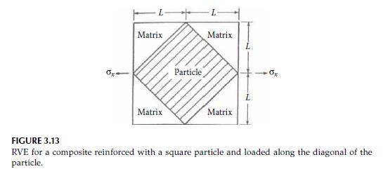
Using the result from Problem 3.9, determine the effective Young's modulus, \(E_{x}\), for the RVE shown in Figure 3.13. In Figure 3.13, the reinforcing particle has a square cross section and is oriented as shown. For a particle having a Young's modulus \(E_{\mathrm{p}}=10 \times 10^{6}
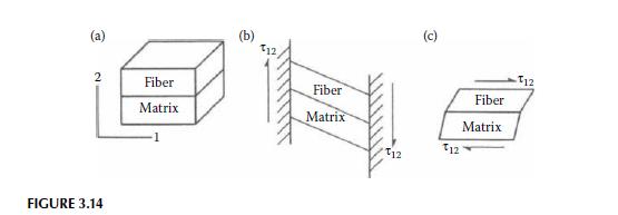
A unidirectional composite is to be modeled by the RVE shown in Figure 3.14a, where the fiber and matrix materials are assumed to be isotropic and perfectly bonded together. Using a mechanics of materials approach, derive the micromechanics equations for the effective in-plane shear modulus,
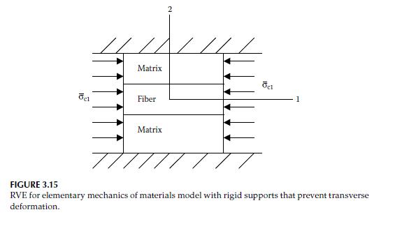
Figure 3.15 shows an RVE for an elementary mechanics of materials model of the same type as shown in Figure 3.7, but with transverse deformation along the 2 direction prevented by rigid supports along the top and bottom edges. For an applied longitudinal normal stress as shown in Figure 3.15, find
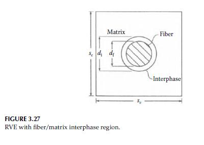
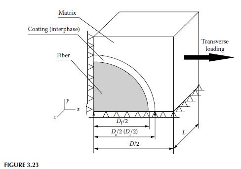
Using the method of subregions, derive an equation for the transverse modulus, \(E_{2}\), for the RVE, which includes a fiber/matrix interphase region, as shown in Figure 3.27. Matrix Fiber Sed d FIGURE 3.27 RVE with fiber/matrix interphase region. Se Interphase
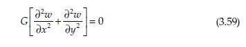
Derive Equation 3.59. me me + ax ay =0 (3.59)
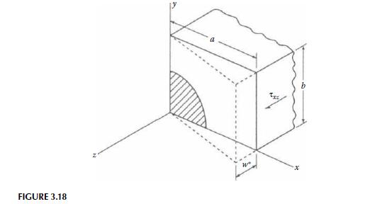
For a unidirectional composite with a rectangular fiber array (Figure 3.18), use the equations of elasticity to set up the displacement boundary value problem for the determination of the transverse modulus, \(E_{2}\). That is, find the governing partial differential equations for displacements
For the quarter domain of an RVE in Figure 3.23, a uniform transverse normal stress \(\bar{\sigma}_{x}\) is applied on the plane \(x=D / 2\). Set up the equations describing the boundary conditions and the constraints on geometrically compatible displacements for a finite element micromechanics
The fibers in a E-glass/epoxy composite are 0.0005 in. \((0.0127 \mathrm{~mm})\) in diameter before coating with an epoxy sizing \(0.0001 \mathrm{in} .(0.00254 \mathrm{~mm})\) thick. After the sizing has been applied, the fibers are bonded together with more epoxy of the same type. What is the
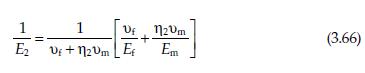
Derive Equation 3.66. Uf 2vm + (3.66) E2 Vi+n2vm Et Em
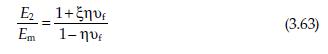
Show that a value of \(\xi=0\) reduces the Halpin-Tsai equation (Equation 3.63) to the inverse rule of mixtures Equation 3.40, whereas a value \(\xi=\infty\) reduces it to the rule of mixtures Equation 3.27. 2 _ 1+ , Em (3.63) 1-
An orthotropic lamina has the following properties:\[E_{1}=160 \mathrm{GPa} \quad s_{\mathrm{L}}^{(+)}=1800 \mathrm{MPa}\]\[\begin{aligned} & E_{2}=10 \mathrm{GPa} \quad s_{\mathrm{L}}^{(-)}=1400 \mathrm{MPa} \\ & v_{12}=0.3 \quad s_{\mathrm{T}}^{(+)}=40 \mathrm{MPa} \\ & G_{12}=7 \mathrm{GPa}
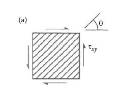
Using the material properties from Problem 4.3 and assuming that the stiffnesses are the same in tension and compression, determine the allowable off-axis shear stress, \(\tau_{x y}\) at \(\theta=45^{\circ}\) (refer to Figure 4.7) according to:(a) the maximum stress criterion,(b) the maximum strain
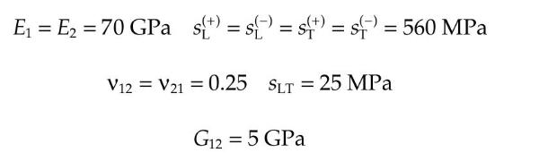
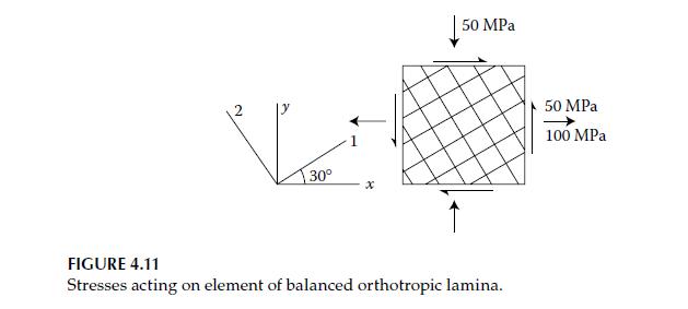
An element of a balanced orthotropic lamina is under the state of stress shown in Figure 4.11. The properties of the lamina are:Using the maximum strain criterion, determine whether or not failure will occur. E = E = 70 GPa s{+) = s{+) = s(+) = s() = 560 MPa V12 V21 0.25 SLT = 25 MPa = G12 = 5 GPa
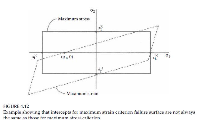
If some of the compliances and strengths of an orthotropic lamina satisfy certain conditions, the maximum strain criterion failure surface will intercept the horizontal axis at a point like \(\left(\sigma_{1}, 0\right)\) instead of at \(\left(s_{\mathrm{L}}^{(-)}, 0\right)\), as shown in Figure
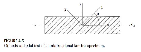
An element of an orthotropic lamina having the properties given in Problem 4.3 is subjected to an off-axis tensile test, as shown in Figure 4.5. Using the maximum strain criterion, determine the values of \(\sigma_{x}\) at failure and the mode of failure for each of the following values of the
Repeat Problem 4.7 for an off-axis compression test.Problem 4.7An element of an orthotropic lamina having the properties given in Problem 4.3 is subjected to an off-axis tensile test, as shown in Figure 4.5. Using the maximum strain criterion, determine the values of \(\sigma_{x}\) at failure and
A material having the properties given in Problem 4.3 is subjected to a biaxial tension test, and the biaxial failure stress is found to be \(\sigma_{1}=\sigma_{2}=35 \mathrm{MPa}\). Determine the Tsai-Wu interaction parameter \(\mathrm{F}_{12}\) and then use the Tsai\(\mathrm{Wu}\) criterion to
The Tsai-Wu interaction parameter \(F_{12}\) is determined from biaxial failure stress data. One way to generate a biaxial state of stress is by using a uniaxial \(45^{\circ}\) off-axis tension test. Derive the expression for \(\mathrm{F}_{12}\) based on such a test, assuming that all the uniaxial
An element of an orthotropic lamina is subjected to an off-axis shear stress, \(\tau_{x y}\), as shown in Figure 4.7a. Using the Tsai-Hill criterion and assuming that the lamina strengths are the same in tension and compression, develop an equation relating the allowable value of \(\tau_{x y}\) to
A uniaxial off-axis tensile test is conducted as shown in Figure 4.5. Using the Tsai-Hill criterion and assuming that the lamina strengths are the same in tension and compression, develop an equation relating the applied stress, \(\sigma_{x^{\prime}}\) to the lamina strengths \(s_{\mathrm{L}},
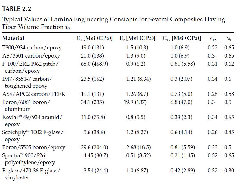
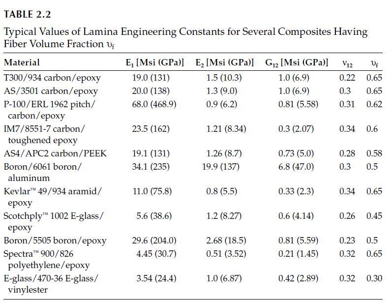
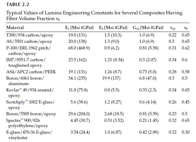
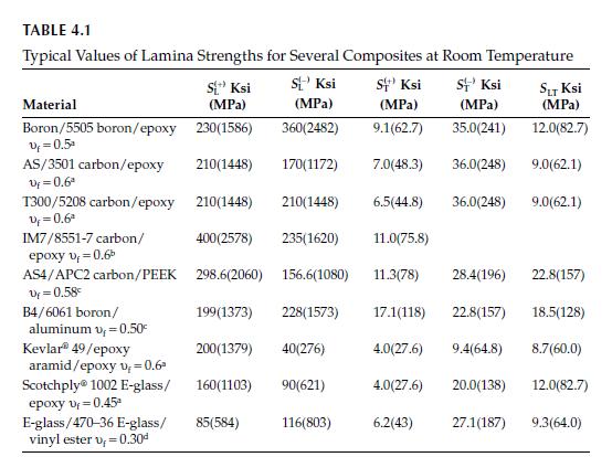
An orthotropic AS/3501 carbon/epoxy lamina (see Tables 2.2 and 4.1) is subjected to the plane stress condition \(\sigma_{x}=1000 \mathrm{MPa}, \sigma_{y}=50 \mathrm{MPa}\), and \(\tau_{x y}=50 \mathrm{MPa}\). If the lamina orientation is \(\theta=0^{\circ}\), will the lamina fail according to (a)
Determine the longitudinal tensile strength of the hybrid carbon/aramid/ epoxy composite described in Problem 3.4 and Figure 3.10 of Chapter 3 if the fiber packing array is square with the closest possible packing.Problem 4.3An orthotropic lamina has the following properties:\[E_{1}=160
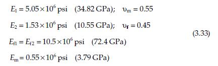
Compare and discuss the estimated longitudinal compressive strengths of Scotchply 1002 E-glass/epoxy based on (a) fiber microbuckling and (b) transverse tensile rupture. Assume linear elastic behavior to failure. For the epoxy matrix, assume that the modulus of elasticity is \(E_{\mathrm{m}}=3.79
Using the maximum strain criterion and micromechanics, set up the equations for predicting the averaged isotropic strength of a randomly oriented continuous fiber composite. Your answer should be expressed in terms of the appropriate fiber and matrix properties and volume fractions, the variable
Assuming that the failure mode for longitudinal compression of unidirectional E-glass/epoxy with fiber volume fraction \(v_{\mathrm{f}}=0.6\) is a transverse tensile rupture due to Poisson strains, (a) estimate the longitudinal compressive strength of this material and (b) if the volume fraction of
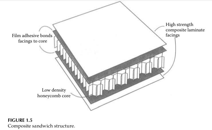
For the IM-9/8551-7 carbon/epoxy composite rod design of Problem 3.3 in Chapter 3, what would be the increase in the longitudinal tensile strength compared with that of the original 6061-T6 aluminum alloy design?Problem 3.3Explain qualitatively why sandwich structures (Figure 1.5) have such high
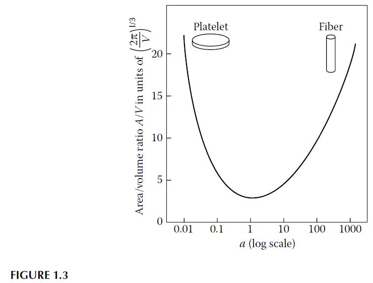
For a cylindrical particle, derive the relationship between the ratio of surface area to volume, A/V, and the particle aspect ratio, l/d, and verify the shape of the curve shown in Figure 1.3. FIGURE 1.3 2 1/3 Area/volume ratio A/V in units of 0 10 10 LO 5 15 20 Platelet Fiber 0.01 0.1 1 10 100
Compare the total surface area of a group of N small-diameter spherical particles with that of a single large-diameter spherical particle having the same volume.
Explain qualitatively why sandwich structures (Figure 1.5) have such high flexural stiffness-to-weight ratios. Describe the key parameters affecting the flexural stiffness-to-weight ratio of a sandwich panel. Film adhesive bonds facings to core High strength composite laminate facings Low density
A support cable in a structure must be 5 m long and must withstand a tensile load of 5 kN with a safety factor of 2.0 against tensile failure. Assuming a solid cylindrical cross section for the cable as an approximation (a) determine and compare the weights of cables made of 4340 steel and AS-4
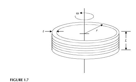
A flywheel for energy storage is modeled as a rotating thin-walled cylindrical ring (t ≪ r) as shown in Figure 1.7. Find the equation for the tensile stress in the ring as a function of the mean radius, r, the rotational speed, ω, and the mass density, ρ, of the ring, then compare the maximum
Describe some practical physical limitations on the use of the RRIM processin molding of chopped FRP matrix composites.
Describe some practical physical limitations on the use of the RTM process in fabrication of composite sandwich structures which consist of composite face sheets and foam or honeycomb core.
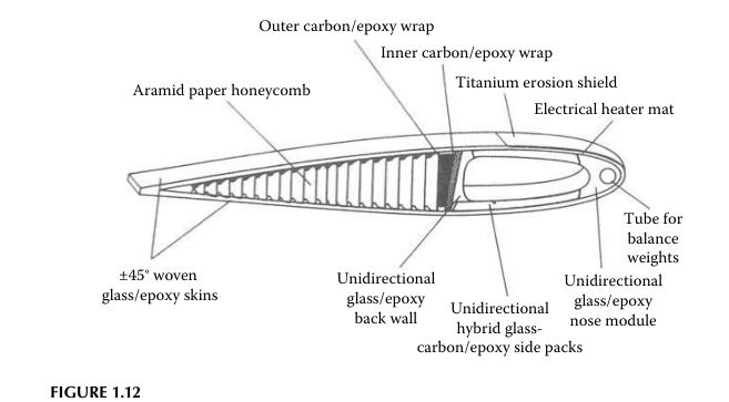
Describe a possible sequence of fabrication processes that might be used to manufacture the helicopter rotor blade in Figure 1.12. Note that several different materials and fiber lay-ups are used. Outer carbon/epoxy wrap Aramid paper honeycomb Inner carbon/epoxy wrap Titanium erosion shield
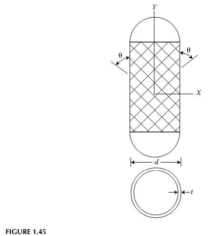
A thin-walled filament-wound composite pressure vessel has fibers wound at a helical angle θ, as shown in Figure 1.45. Ignore the resin matrix material and assume that the fibers carry the entire load. Also assume that all fibers are uniformly stressed in tension. This gross oversimplification is
A filament-wound E-glass/epoxy pressure vessel has a diameter of 50 in. (127 cm), a wall thickness of 0.25 in. (6.35 mm), and a helical wrap angle θ = 54.74°. Using a netting analysis and a safety factor of 2, estimate the allowable internal pressure in the vessel. Compare with the allowable
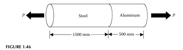
The 2000 mm long composite bar shown in Figure 1.46 consists of an aluminum bar having a modulus of elasticity EAl = 70 GPa and length LAl = 500 mm, which is securely fastened to a steel bar having modulus of elasticity ESt = 210 GPa and length LSt = 1500 mm. After the force P is applied, a
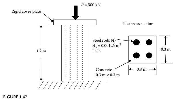
The concrete composite post in Figure 1.47 is 1.2 m long with a 0.3 m × 0.3 m square cross section. The post is reinforced by four vertical steel rods of the same length having a cross-sectional area of As = 0.00125 m2 each, and is loaded by a single vertical load P = 500 kN applied on the rigid
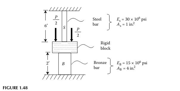
The composite bar system in Figure 1.48 consists of a steel bar and a bronze bar that are both securely attached to a rigid block and rigid supports. The system is loaded with a total load P at the rigid block. If the total applied load is P = 42,000 lb, determine the stresses in the two bars.
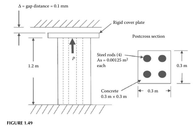
The composite post in Figure 1.49 has the same properties and dimensions as in Problem 1.13, except that there is a gap Δ = 0.1 mm between the top of the cover plate on the post and the upper support. An upward load P is applied to the rigid cover plate, which is securely attached to the concrete
For the original concrete composite post design of Problem 1.13, assume that the steel rods are made of 4340 steel, and that the rods are to be replaced by IM9 carbon fiber bundles of the same length in a new design. The new design also calls for the load and deformation in the carbon fiber
For the original 4340 steel-reinforced concrete post design of Problem 1.13 and the new IM9 carbon fiber-reinforced concrete post design of Problem 1.16, compare the tensile stress-to-tensile strength ratio for the steel rod with the corresponding stress-to-strength ratio for the carbon fiber
Using an example of static equilibrium of an element in pure two-dimensional (2D) shear stress, prove that the shear stresses are symmetric (i.e., prove that \(\sigma_{i j}=\sigma_{j i}\) when \(i eq j\) ).
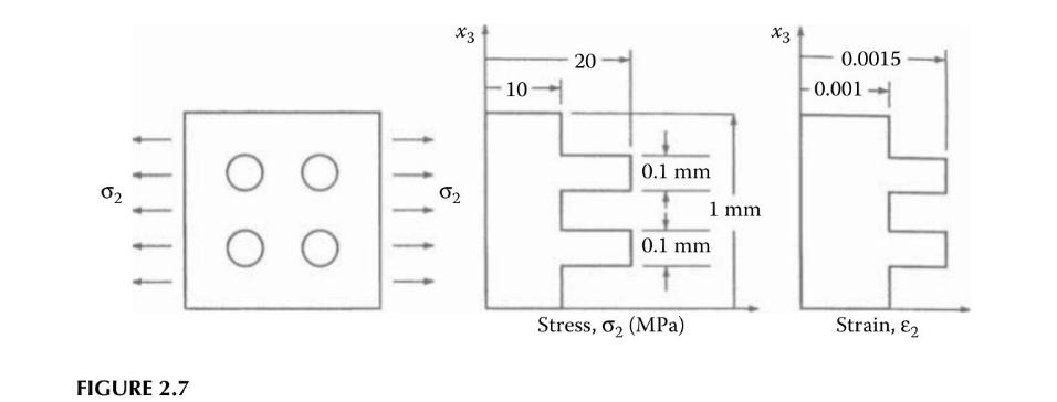
A representative section from a composite lamina is shown in Figure 2.7 along with the transverse stress and strain distributions across the fiber and matrix materials in the section. The composite section is \(1 \times 1 \mathrm{~mm}\) square, and the diameter of each of the four fibers is \(0.1
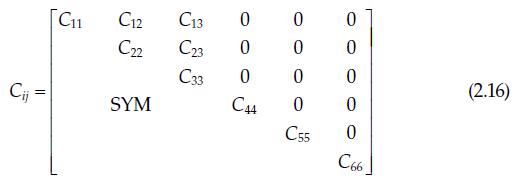
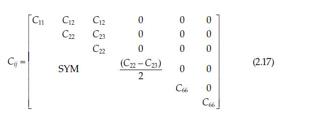
The stiffness matrix \([C]\) for a specially orthotropic material associated with the principal material axes \((1,2,3)\) is given in Equation 2.16. Prove that, when the material is specially orthotropic and transversely isotropic in the 2-3 planes (i.e., the properties are invariant to rotations
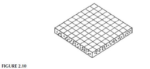
A balanced orthotropic, or square symmetric lamina, is made up of \(0^{\circ}\) and \(90^{\circ}\) fibers woven into a fabric and bonded together, as shown in Figure 2.10.a. Describe the stress-strain relationships for such a lamina in terms of the appropriate engineering constants.b. For a typical
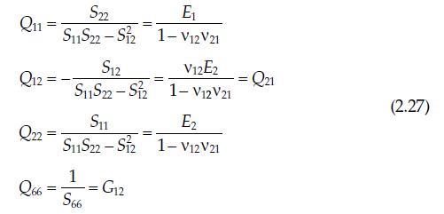
Derive Equation 2.27. = S22 E S11S22 S2 1-V12V21 - S12 V12E2 SS22 S2 1-V12V21 S11 - S11S22-S2 1 = == S66 G12 = E2 1-V12V21 Q11 = Q12= Q22 Q66 = Q21 (2.27)
Find all components of the stiffness and compliance matrices for a specially orthotropic lamina made of AS/3501 carbon/epoxy.
For a specially orthotropic, transversely isotropic material the "plane strain bulk modulus," \(K_{23}\), is an engineering constant that is defined by the stress conditions \(\sigma_{2}=\sigma_{3}=\sigma\) and the strain conditions \(\varepsilon_{1}=0,
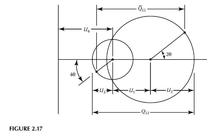
Describe the measurements that would have to be taken and the equations that would have to be used to determine \(G_{23}, v_{32}\), and \(E_{2}\) for a specially orthotropic, transversely isotropic material from a single tensile test. can be represented graphically by using two Mohr's circles, as
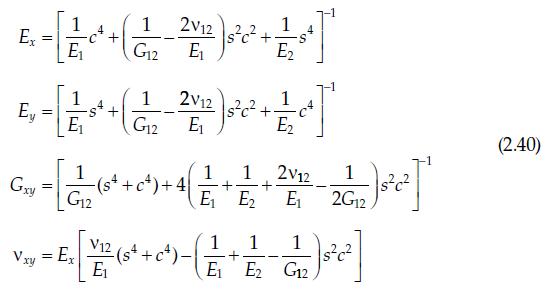
Derive the first of Equation 2.40 for the off-axis modulus, \(E_{x}\). 2V12 E-[1 + (1-2)+1] Ex = Ey E E 1 2V12 + 1 1 G12 E2 1 E2 2V12 - E 2G12 1 1 sc E E1 E2 E2 G12 Gxy = 1 G12 Vxy = Ex ($4 V12 +c c). +4 1 1 1 + -c)- + 1 2 + 1 (2.40)
Showing 100 - 200
of 214
1
2
3
Step by Step Answers