New Semester
Started
Get
50% OFF
Study Help!
--h --m --s
Claim Now
Question Answers
Textbooks
Find textbooks, questions and answers
Oops, something went wrong!
Change your search query and then try again
S
Books
FREE
Study Help
Expert Questions
Accounting
General Management
Mathematics
Finance
Organizational Behaviour
Law
Physics
Operating System
Management Leadership
Sociology
Programming
Marketing
Database
Computer Network
Economics
Textbooks Solutions
Accounting
Managerial Accounting
Management Leadership
Cost Accounting
Statistics
Business Law
Corporate Finance
Finance
Economics
Auditing
Tutors
Online Tutors
Find a Tutor
Hire a Tutor
Become a Tutor
AI Tutor
AI Study Planner
NEW
Sell Books
Search
Search
Sign In
Register
study help
engineering
principles of geotechnical engineering
Principles Of Geotechnical Engineering 10th Edition Braja M. Das - Solutions
The porosity of a soil is 0.35. Given Gs = 2.69, calculate:a. Saturated unit weight (kN/m3)b. Moisture content when moist unit weight = 17.5 kN/m3
A saturated soil has ω = 23% and Gs = 2.62. Determine its saturated and dry densities in kg/m3.
A soil has e = 0.75, ω = 21.5%, and Gs = 2.71. Determine:a. Moist unit weight (lb/ft3)b. Dry unit weight (lb/ft3)c. Degree of saturation (%)
The moist unit weights and degrees of saturation of a soil are given in the table.Determine:a. eb. Gs y (lb/ft³) 105.73 112.67 S (%) 50 75
A soil has ω = 18.2%, Gs = 2.67, and S = 80%. Determine the moist and dry unit weights of the soil in lb/ft3.
Refer to Problem 3.16. Determine the weight of water, in lb, that will be in 2.5 ft3 of the soil when saturated.Data From Problem 3.16The moist unit weights and degrees of saturation of a soil are given in the table.Determine:a. eb. Gs y (lb/ft³) 105.73 112.67 S (%) 50 75
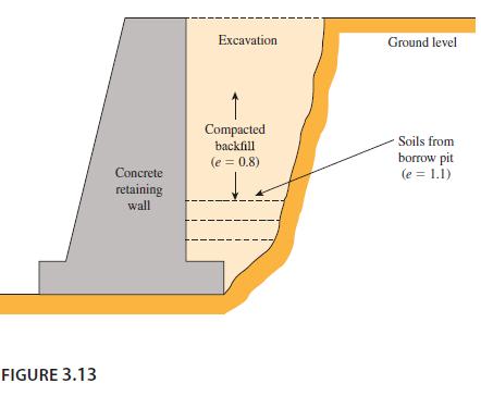
Refer to Figure 3.13. After the construction of a concrete retaining wall, backfill material from a nearby borrow pit was brought into the excavation behind the wall and compacted to a final void ratio of 0.8. Given that the soil in the borrow pit has a void ratio of 1.1, determine the volume of
Refer to Problem 3.18. Given that the borrow pit has a moisture content of 11% and Gs = 2.7, determine:a. Moist unit weight of the borrow soilb. Degree of saturation of the borrow soilc. Moist unit weight of the compacted backfillData From Problem 3.18Refer to Figure 3.13. After the
For a given sand, the maximum and minimum void ratios are 0.78 and 0.43, respectively. Given Gs = 2.67, determine the dry unit weight of the soil in kN/m3 when the relative density is 65%.
For a given sandy soil, emax = 0.75, emin = 0.46, and Gs = 2.68. What will be the moist unit weight of compaction (kN/m3) in the field if Dr = 78% and ω = 9%?
For a given sandy soil, the maximum and minimum dry unit weights are 108 lb/ft3 and 92 lb/ft3, respectively. Given Gs = 2.65, determine the moist unit weight of this soil when the relative density is 60% and the moisture content is 8%.
The moisture content of a soil sample is 18.4%, and its dry unit weight is 100 lb/ft3. Assuming that the specific gravity of solids is 2.65,a. Calculate the degree of saturation.b. What is the maximum dry unit weight to which this soil can be compacted without change in its moisture content?
A loose, uncompacted sand fill 6 ft in depth has a relative density of 40%. Laboratory tests indicated that the minimum and maximum void ratios of the sand are 0.46 and 0.90, respectively. The specific gravity of solids of the sand is 2.65.a. What is the dry unit weight of the sand?b. If the sand
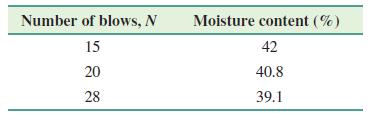
Results from liquid and plastic limit tests conducted on a soil are given here.Liquid limit tests:Plastic limit tests: PL = 18.7%a. Draw the flow curve and obtain the liquid limit.b. What is the plasticity index of the soil? Number of blows, N 15 20 28 Moisture content (%) 42 40.8 39.1
Refer to Problem 4.3. Determine the liquidity index of the soil when the in situ moisture content is 26%.Data From Problem 4.3Results from liquid and plastic limit tests conducted on a soil are given here.Liquid limit tests:Plastic limit tests: PL = 18.7%a. Draw the flow curve and obtain the liquid
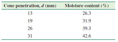
The following results were obtained for a liquid limit test using a fall cone device. Estimate the liquid limit of the soil and the flow index. Cone penetration, d (mm) 13 19 26 31 Moisture content (%) 26.3 31.9 39.3 42.6
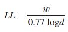
Refer to the same soil in Problem 4.7. A single test was conducted with the fall cone device, and the following results were obtained: d =17 mm and ω = 28.5%. Using Eqs. (4.5), (4.6), and (4.7), estimate the liquid limit by the one point method.Eqs. (4.5)Eqs (4.6)Eqs (4.7)Data From Problem 4.7The
Consider Soil No. 3 of Problem 4.9. Using the % of clay size fraction and the liquid limit of the soil, estimate:a. Plastic limit (use Eq. 4.10)b. Plasticity index (use Eq. 4.11)c. Activity (use Eq. 4.19)Data From Problem 4.9Liquidity index, LI, defined by Eq. (4.15), can indicate probable
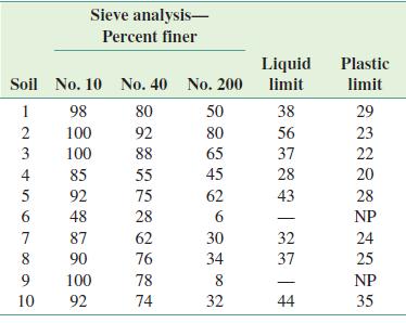
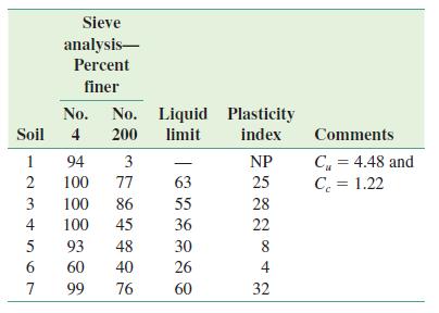
The sieve analysis of ten soils and the liquid and plastic limits of the fraction passing through the No. 40 sieve are given here. Classify the soils using the AASHTO soil classification system and give the group indexes. Sieve analysis- Percent finer Soil No.
Classify the following soils using the Unified soil classification system. Give group symbols and group names. No. No. Liquid Plasticity Soil 4 200 limit index 1 2 3 4 5 6 Sieve analysis- Percent finer 7 94 3 100 77 63 86 55 36 30 26 60 100 100 45 93 48 60 40 99
Given Gs = 2.75, calculate the zero-air-void unit weight in lb/ft3 for a soil at ω = 5%, 8%, 10%, 12%, and 15%.
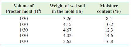
The results of a standard Proctor test are given here. Determine the maximum dry unit weight of compaction and the optimum moisture content. Volume of Proctor mold (ft³) 1/30 1/30 1/30 1/30 1/30 Weight of wet soil in the mold (lb) 3.26 4.15 4.67 4.02 3.63 Moisture content
Calculate the variation of dry density (kg/m3) of a soil (Gs = 2.67) at ω = 10% and 20% for degree of saturation (S) = 80%, 90%, and 100%.
For the soil described in Problem 6.3, if Gs = 2.72, determine the void ratio and degree of saturation at optimum moisture content.Data From Problem 6.3The results of a standard Proctor test are given here. Determine the maximum dry unit weight of compaction and the optimum moisture content. Volume
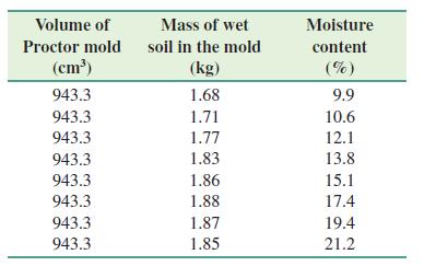
The results of a standard Proctor test are given in the following table. Determine the maximum dry density (kg/m3) of compaction and the optimum moisture content. Volume of Proctor mold (cm³) 943.3 943.3 943.3 943.3 943.3 943.3 943.3 943.3 Mass of wet soil in the
A field unit weight determination test for the soil described in Problem 6.5 yielded the following data: moisture content = 10.5% and moist density = 1705 kg/m3. Determine the relative compaction.Data From Problem 6.5 The results of a standard Proctor test are given in the following table.
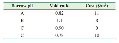
A proposed embankment fill requires 8000 m3 of compacted soil. The void ratio of the compacted fill is specified as 0.7. Four borrow pits are available as described in the following table, which lists the respective void ratios of the soil and the cost per cubic meter for moving the soil to the
The in situ moisture content of a soil is 18%, and the moist unit weight is 105 lb/ft3. The specific gravity of soil solids is 2.75. This soil is to be excavated and transported to a construction site for use in a compacted fill. If the specifications call for the soil to be compacted to a minimum
For a clayey soil, given: LL = 38, PI = 16, and Gs = 2.68. If a modified Proctor test is conducted, estimate wopt and γd(max)γw. Use the method of Gurtug and Sridharan (2004).
Repeat Problem 6.9 using Matteo’s (2009) method.Data From Problem 6.9For a clayey soil, given: LL = 38, PI = 16, and Gs = 2.68. If a modified Proctor test is conducted, estimate wopt and γd(max)γw. Use the method of Gurtug and Sridharan (2004).
The maximum and minimum dry unit weights of a sand were determined in the laboratory to be 104 lb/ft3 and 93 lb/ft3, respectively. What would be the relative compaction in the field if the relative density is 78%?
The maximum and minimum dry densities of a sand were determined in the laboratory to be 1682 kg/m3 and 1510 kg/m3, respectively. In the field, if the relative density of compaction of the same sand is 70%, what are its relative compaction (%) and dry density (kg/m3)?
The relative compaction of a sand in the field is 90%. The maximum and minimum dry unit weights of the sand are 108 lb/ft3 and 93 lb/ft3, respectively. For the field conditions, determine:a. Dry unit weightb. Relative density of compactionc. Moist unit weight at a moisture content of 12%
Following are the results of a field unit weight determination test on a soil using the sand cone method.Calibrated dry density of Ottawa sand = 1667 kg /m3Calibrated mass of Ottawa sand to fill the cone = 0.117 kgMass of jar + cone + sand (before use) = 5.99 kgMass of jar + cone + sand (after use)
The backfill material for a vibroflotation project has the following grain sizes.D10 = 0.11 mmD20 = 0.19 mmD50 = 1.3 mmDetermine the suitability number, SN, for each.
Repeat Problem 6.15 with the following values.D10 = 0.09 mmD20 = 0.25 mmD50 = 0.61 mmData From Problem 6.15The backfill material for a vibroflotation project has the followinggrain sizes.D10 = 0.11 mmD20 = 0.19 mmD50 = 1.3 mmDetermine the suitability number, SN, for each.
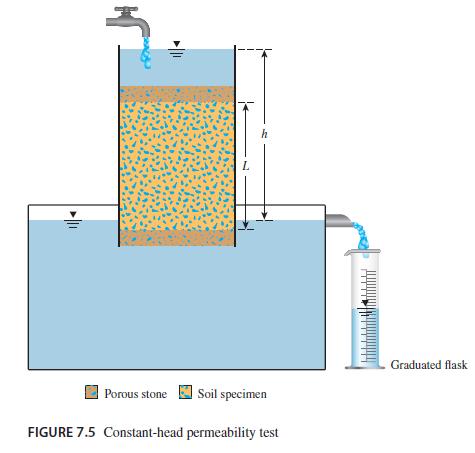
Refer to the constant-head arrangement shown in Figure 7.5. For a test, the following are given:L = 450 mmA = area of the specimen = 23 cm2Constant-head difference = h = 700 mmWater collected in 3 min = 350 cm3 Porous stone L h Soil specimen FIGURE 7.5 Constant-head permeability test Graduated flask
Refer to Figure 7.5. For a constant-head permeability test in a sand, the following are given:L = 300 mmA = 175 cm2h = 500 mmWater collected in 3 min = 620 cm3Void ratio of sand = 0.58Determine:a. Hydraulic conductivity, k (cm/s)b. Seepage velocity Porous stone L h Soil specimen FIGURE 7.5
In a constant-head permeability test in the laboratory, the following are given: L = 305 mm and A = 95 cm2. If the value of k = 0.015 cm/s and a flow rate of 7300 cm3/hr must be maintained through the soil, what is the head difference, h, across the specimen? Also, determine the discharge velocity
For a falling-head permeability test, the following are given:Length of the soil specimen = 500 mmArea of the soil specimen = 26 cm2Area of the standpipe= 1.3 cm2Head difference at time t = 0 is 760 mmHead difference at time t = 10 min is 300 mma. Determine the hydraulic conductivity of the soil
For a falling-head permeability test, the following are given: length of specimen = 380 mm; area of specimen = 6.5 cm2; k = 0.175 cm/min. What should the area of the standpipe be for the head to drop from 650 cm to 300 cm in 8 min?
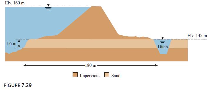
A sand layer of the cross-sectional area shown in Figure 7.29 has been determined to exist for an 800 m length of the levee. The hydraulic conductivity of the sand layer is 2.8 m/day. Determine the quantity of water which flows into the ditch in m3/min. Elv. 160 m 1.6 m 1 FIGURE 7.29 -180
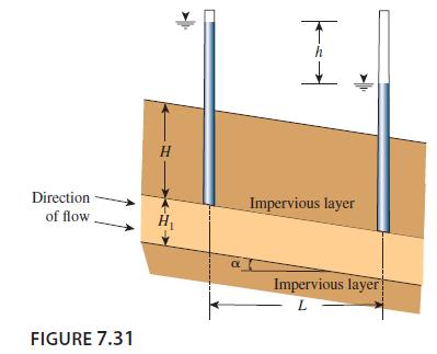
Refer to Figure 7.31. Find the flow rate in m3/s/m (at right angles to the cross section shown) through the permeable soil layer. Given: H = 5 m, H1 = 2.8 m; h = 3.1 m, L = 60 m, α = 5°, and k = 0.05 cm/s. Direction of flow FIGURE 7.31 H h Impervious layer Impervious layer L
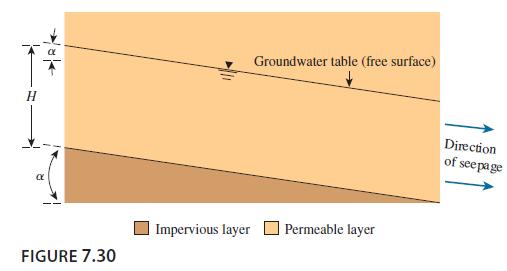
A permeable layer is underlain by an impervious layer, as shown in Figure 7.30. With k = 5.2 X 10⁻⁴ cm/s for the permeable layer, calculate the rate of seepage through it in m3/hr/m if H = 3.8 m and α = 12°. FIGURE 7.30 Groundwater table (free surface) Impervious layer Permeable
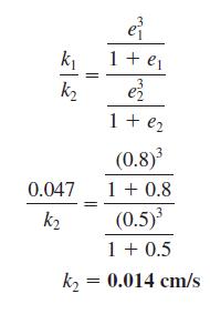
The hydraulic conductivity of a sand at a void ratio of 0.5 is 0.022 cm/s. Estimate its hydraulic conductivity at a void ratio of 0.7. Use Eq. (7.31). k₁ k₂ 0.047 k₂ e² 1 + ₁ 1 + €₂ (0.8)³ 1 + 0.8 (0.5)³ 1 + 0.5 k₂ = 0.014 cm/s
For a falling-head permeability test, the following are given:Length of the soil specimen = 700 mmArea of the soil specimen = 20 cm2Area of the standpipe = 1.05 cm2Head difference at time t = 0 is 800 mmHead difference at time t = 8 min is 500 mma. Determine the absolute permeability of the soil.b.
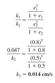
For a sand, the following are given: porosity, n = 0.31 and k = 6.1 cm/min. Determine k when n = 0.4. Use Eq. (7.31). k₁ k₂ e² 1 + ₁ 1 + €₂ (0.8)³ 1 + 0.8 (0.5)³ 1 + 0.5 k₂ = 0.014 cm/s 0.047 k₂
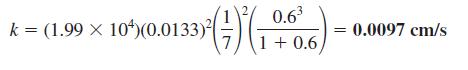
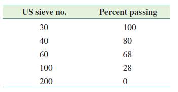
The sieve analysis for a sand is given in the following table. Estimate the hydraulic conductivity of the sand at a void ratio of 0.5. Use Eq. (7.30) and SF = 6.5. k = (1.99 x 10) (0.0133)² 10%)(0.0133) 0.6³ 1+0.6) 0.0097 cm/s
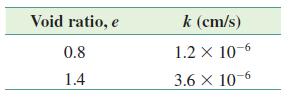
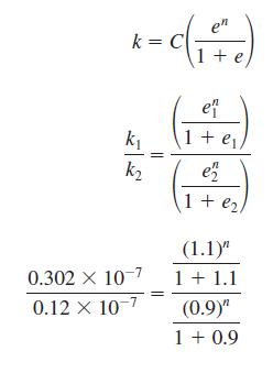
For a normally consolidated clay, the following are given:Estimate the hydraulic conductivity at a void ratio e = 0.9. Use Eq. (7.36). Void ratio, e 0.8 1.4 k (cm/s) 1.2 x 10⁻⁶ 3.6 x 10⁻⁶
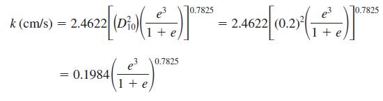
For a sandy soil, the following are given:Maximum void ratio = 0.7Minimum void ratio = 0.46D10 = 0.2 mmDetermine the hydraulic conductivity of the sand at a relative density of 60%. Use Eq. (7.32). 0.7825 - 2.4622 (1)(*)-24622(2)(1) = k (cm/s) = 2.4622| 1+ 3 984) 1+ £ = 0.1984 0.7825 £ 0.7825
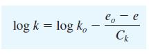
The in situ void ratio of a soft clay deposit is 2.1, and the hydraulic conductivity of the clay at this void ratio is 0.91 X 10⁻⁶ cm/s. What is the hydraulic conductivity if the soil is compressed to have a void ratio of 1.1? Use Eq. (7.34). log k = log ko eo - e lo Ck
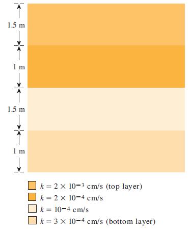
A layered soil is shown in Figure 7.33. Estimate the ratio of equivalent hydraulic conductivity, kH(eq) /kV(eq). K 1.5 m 1 m 1.5 m 1 m k = 2 x 10⁻³ cm/s (top layer) k = 2 x 10⁻⁴ cm/s k = 10-4 cm/s k = 3 x 10⁻⁴ cm/s (bottom layer)
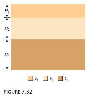
A layered soil is shown in Figure 7.32. Given:H1 = 1.5 m k1 = 10-5 cm/sH2 = 2.5 m k2 = 3.0 X 10⁻³ cm/sH3 = 3.0 m k3 = 3.5 X 10⁻⁵ cm/sEstimate the ratio of equivalent permeability, kH(eq) /kV(eq). KE★ H₂ H3 ] ki FIGURE 7.32 k3
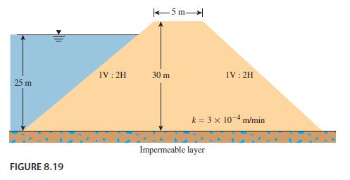
Refer to the cross section of the earth dam shown in Figure 8.19. Calculate the rate of seepage through the dam (q in m3/min/m) using Schaffernak’s solution. 25 m FIGURE 8.19 IV: 2H 5 m- 30 m IV: 2H k= 3 x 10⁻⁴ m/min Impermeable layer
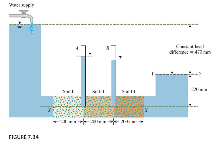
Consider the setup shown in Figure 7.34 in which three different soil layers, each 200 mm in length, are located inside a cylindrical tube of diameter 150 mm. A constant-head difference of 470 mm is maintained across the soil sample. The porosities and hydraulic conductivities of the three soils in
Solve Problem 8.10 using L. Casagrande’s method.Data From Problem 8.10Refer to the cross section of the earth dam shown in Figure 8.19. Calculate the rate of seepage through the dam (q in m3/min/m) using Schaffernak’s solution. 25 m FIGURE 8.19 IV: 2H 5 m- 30 m IV: 2H k= 3 x 10⁻⁴
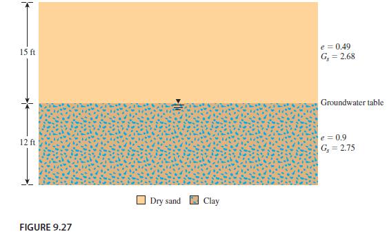
Refer to the soil profile shown in Figure 9.27.a. Calculate the variation of σ, u, and σ with depth.b. If the water table rises to the top of the ground surface, what is the change in the effective stress at the bottom of the clay layer?c. How many feet must the groundwater table rise to decrease
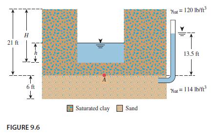
Refer to Problem 9.6. It is required to make an open excavation of 18 ft in the saturated clay. To avoid heaving, the cut will be filled with water similar to that shown in Figure 9.6. What should be the height of water, h, in the excavation? 21 ft H 6 ft ↓ FIGURE 9.6 Saturated clay Sand Ysat =
A sand has Gs = 2.68. Calculate the hydraulic gradient that will cause boiling for e = 0.4, 0.5, 0.6, and 0.7. Plot a graph for icr versus e.
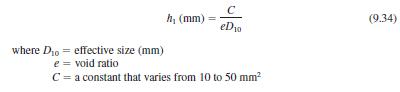
From the sieve analysis of a sand, the effective size was determined to be 0.18 mm. Using Hazen’s formula, Eq. (9.34), estimate the range of capillary rise in this sand for a void ratio of 0.65. h, (mm) C eD₂0 where Dio effective size (mm) e = void ratio C = a constant that varies from 10 to 50
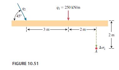
Refer to Figure 10.51. Due to the application of line loads q1 and q2, the vertical stress increase, Dsz, at A is 30 kN/m2. Determine the magnitude of q2. 45° 92 FIGURE 10.51 3 m. 91 = 250 kN/m 2m- A Aσ₂ 2m ↓
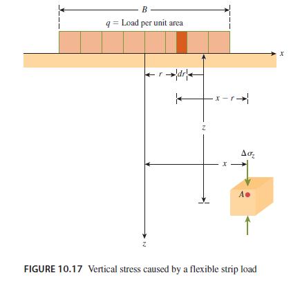
Refer to Figure 10.17. Given: B = 3.7 m, q = 16.8 kN/m2, x = 2.7 m, and z = 1.5 m. Determine the vertical stress increase, Δσz at Point A. B- q= Load per unit area r dry Z X r. x. Aσ₂ A. А FIGURE 10.17 Vertical stress caused by a flexible strip load 3
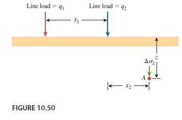
Refer to Figure 10.50. Given: q1 = 10.9 kN/m, x1 = 2.45 m, x2 = 1.22 m, and z = 0.9 m. If the vertical stress at point A due to the loading is 1.7 kN/m2, determine the magnitude of q2. Line load = 91 FIGURE 10.50 X₁ Line load = 92 X2 Z Aσ₂
Repeat Problem 10.12 for B = 3 m, q = 60 kN/m2, x = 1.5 m, and z = 3 m.Data From Problem 10.12Refer to Figure 10.17. Given: B = 3.7 m, q = 16.8 kN/m2, x = 2.7 m, and z = 1.5 m. Determine the vertical stress increase, Δσz at Point A. B- q= Load per unit
Refer to Figure 9.5 a. If H1 = 0.6 m, H2 = 1 m, h = 0.4 m, γsat = 18.6 kN/m3, hydraulic conductivity of sand (k) = 0.12 cm/s, and area of tank = 0.45 m2, what is the rate of upward seepage of the water (m3/min)?
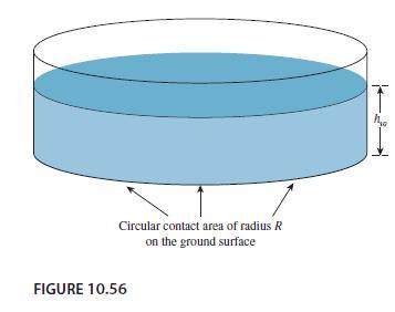
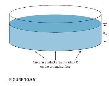
Refer to Figure 10.56. If R = 4 m and hw = height of water 5 = m, determine the vertical stress increases 2 m below the loaded area at radial distances where r = 0, 2, 4, 6, and 8 m. Circular contact area of radius R on the ground surface FIGURE 10.56 h
Figure 10.56 shows the schematic of a circular water storage facility resting on the ground surface. The radius of the storage tank is R = 2.5 m and the maximum height of water is hw = 4 m. Determine the vertical stress increase, Δσz at points 0, 2, 4, 8, and 10 m below the ground surface
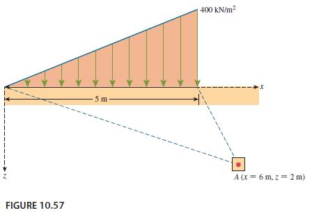
Refer to Figure 10.57. For the linearly increasing vertical loading on an infinite strip of width 5 m, determine the vertical stress increase, Δσz at A. FIGURE 10.57 5 m 400 kN/m² 1 A (x = 6 m, z = 2 m)
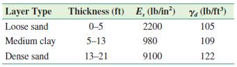
A rigid, reinforced concrete foundation is subjected to a column load of 87,000 lb. The foundation plan measures 8 ft X 8 ft and rests on 21 ft (= H') of layered soil underlain by rock. The soil layers have the following characteristics.If the footing depth Df = 4 ft and μs = 0.4 for all
A shallow foundation supported by a silty sand is shown inFigure 11.6. Given:Length: L = 3 mWidth: B = 3 mDepth of foundation: Df = 1.5 mThickness of foundation: t = 0.25 mLoad per unit area: Ds = 150 kN/m2Ef = 15 X 106 kN/m2The silty sand has the following properties.H' = 20
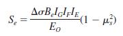
Figure 10.31 shows a flexible circular area of radius R = 3 m. The uniformly distributed load on the circular area is 96 kN/m2. Calculate the vertical stress increase at r = 0, 0.6, 1.2, 2.4, and 3.6 with z = 1.5 m. 9 M 1 1 1 N Aσ₂ Aσ₂ FIGURE 10.31 Vertical stress at any point below
Consider a circularly loaded flexible area on the ground surface. Given the radius of the circular area R = 4 m and the uniformly distributed load q = 200 kN/m2, calculate the vertical stress increase, Δσz, at points 1.5, 3, 6, 9, and 12 m below the ground surface (immediately below the center of
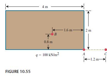
The plan of a flexible rectangular loaded area is shown in Figure 10.55. The uniformly distributed load on the flexible area, a, is 100 kN/m2. Determine the increase in the vertical stress, Δσz, at a depth of z = 2 m below the following.a. Point Ab. Point Bc. Point C FIGURE 10.55 4 m 0.8 m B q=
Showing 100 - 200
of 173
1
2
Step by Step Answers