New Semester
Started
Get
50% OFF
Study Help!
--h --m --s
Claim Now
Question Answers
Textbooks
Find textbooks, questions and answers
Oops, something went wrong!
Change your search query and then try again
S
Books
FREE
Study Help
Expert Questions
Accounting
General Management
Mathematics
Finance
Organizational Behaviour
Law
Physics
Operating System
Management Leadership
Sociology
Programming
Marketing
Database
Computer Network
Economics
Textbooks Solutions
Accounting
Managerial Accounting
Management Leadership
Cost Accounting
Statistics
Business Law
Corporate Finance
Finance
Economics
Auditing
Tutors
Online Tutors
Find a Tutor
Hire a Tutor
Become a Tutor
AI Tutor
AI Study Planner
NEW
Sell Books
Search
Search
Sign In
Register
study help
engineering
structural analysis
Structural Analysis 10th Edition Russell Hibbeler - Solutions
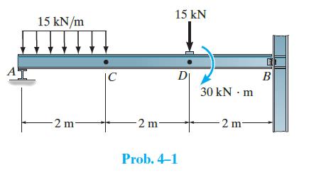
Determine the internal normal force, shear force, and bending moment in the beam at points C and D. Point D is located just to the right of the concentrated force and moment. Assume the support at B is a pin and A is a roller. A 15 kN/m -2 m- C -2 m 15 kN Di Prob. 4-1 30 kN - m 2 m B
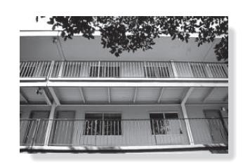
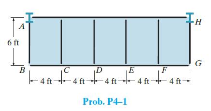
The balcony located on the third floor of a motel is shown in the photo. It is constructed using a 4-in.-thick concrete (plain stone) slab which rests on the four simply supported floor beams, two cantilevered side girders AB and HG, and the front and rear girders. The idealized framing plan with
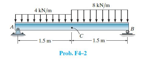
Determine the internal normal force, shear force, and bending moment acting at point C in the beam. A 4 kN/m 1.5 m- Ic Prob. F4-2 8 kN/m -1.5 m B
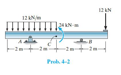
Determine the internal normal force, shear force, and bending moment at point C. Point C is located just to the left of the moment. 12 kN/m A -2m 24 kN-m 4 C 2 m 12 kN - B -2m-2m- Prob. 4-2
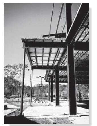
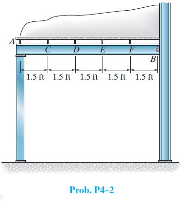
The canopy shown in the photo provides shelter for the entrance of a building. Consider all members to be simply supported. The bar joists at C, D, E, F each have a weight of 135 lb and are 20 ft long. The roof is 4 in. thick and is to be plain lightweight concrete having a density of 102 lb/ft3.
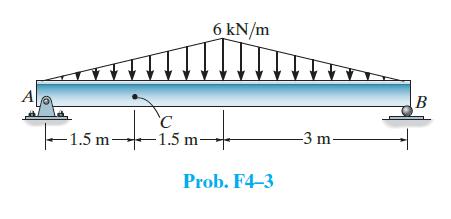
Determine the internal normal force, shear force, and bending moment acting at point C in the beam. -1.5m C -1.5 m 6 kN/m Prob. F4-3 -3 m- B
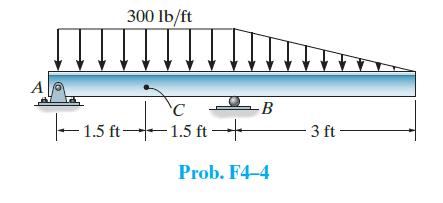
Determine the internal normal force, shear force, and bending moment acting at point C in the beam. A 300 lb/ft 'C 1.5 ft 1.5 ft- -B Prob. F4-4 3 ft
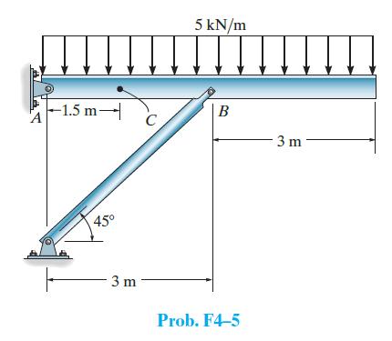
Determine the internal normal force, shear force, and bending moment acting at point C in the beam. A -1.5 m- 45° -3 m C 5 kN/m B Prob. F4-5 3 m
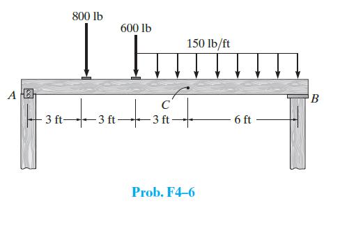
Determine the internal normal force, shear force, and bending moment acting at point C in the beam. A B 3 ft- 800 lb 600 lb -3 ft- C -3 ft- 150 lb/ft Prob. F4-6 6 ft B
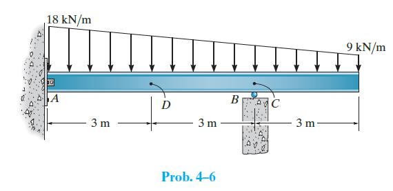
Determine the internal normal force, shear force, and bending moment in the beam at points C and D. Point C is located just to the left of the roller support. Assume the support at B is a roller and A is a pin. 18 kN/m 10 A 3 m D 3 m Prob. 4-6 B la 3 m 9 kN/m
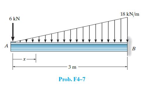
Determine the internal shear and moment in the beam as a function of x. A 6 kN -3 m Prob. F4-7 18 kN/m B
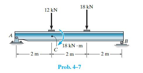
Determine the internal normal force, shear force, and bending moment acting at point C, located just to the right of the 12-kN force and 18 kN · m moment. 2 m 12 kN 18 kN 18 kN m 2 m Prob. 4-7 -2m B
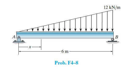
Determine the internal shear and moment in the beam as a function of x. A ·x 6 m Prob. F4-8 12 kN/m B
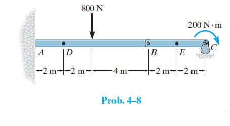
Determine the internal normal force, shear force, and moment at points E and D of the compound beam. D 800 N A -2 m--2 m- -4 m- Prob. 4-8 B 200 N·m E 40528 +2m-2 m-
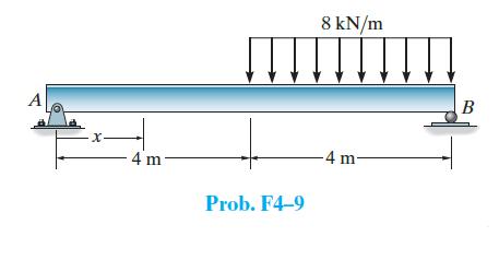
Determine the internal shear and moment in the beam as a function of x throughout the beam. A X- 4 -4 m- Prob. F4-9 8 kN/m -4 m- B
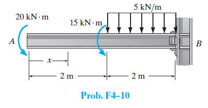
Determine the internal shear and moment in the beam as a function of x throughout the beam. 20 kN.m A X- 15 kN m - 2 m Prob. F4-10 5 kN/m 2m jooo B
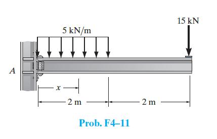
Determine the internal shear and moment in the beam as a function of x throughout the beam. A 5 kN/m X 4 -2 m Prob. F4-11 2 m 15 kN
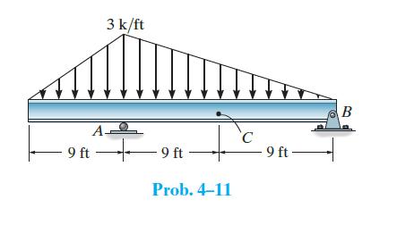
Determine the internal normal force, shear force, and bending moment in the beam at point C. A 9 ft 3 k/ft 9 ft Ic C Prob. 4-11 -9 ft- B
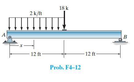
Determine the internal shear and moment in the beam as a function of x throughout the beam. X 2 k/ft 12 ft- 18 k Prob. F4-12 -12 ft- B
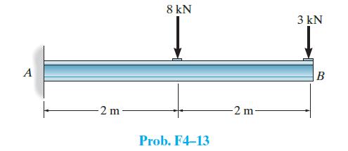
Draw the shear and moment diagrams for the beam. Indicate values at the supports and at the points where a change in load occurs. A -2 m 8 kN Prob. F4-13 -2 m 3 kN B
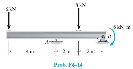
Draw the shear and moment diagrams for the beam. Indicate values at the supports and at the points where a change in load occurs. 6 kN -4 m- A- 8 kN + + -2 m Prob. F4-14 2 m B 6 kN.m
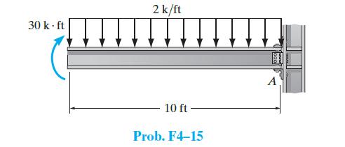
Draw the shear and moment diagrams for the beam. Indicate values at the supports and at the points where a change in load occurs. 30 k-ft 2 k/ft 10 ft Prob. F4-15 A
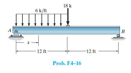
Draw the shear and moment diagrams for the beam. Indicate values at the supports and at the points where a change in load occurs. A X 6 k/ft 12 ft 18 k Prob. F4-16 -12 ft B
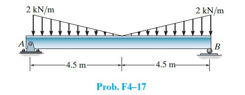
Draw the shear and moment diagrams for the beam. Indicate values at the supports and at the points where a change in load occurs. 2 kN/m -4.5 m- + Prob. F4-17 -4.5 m- 2 kN/m B
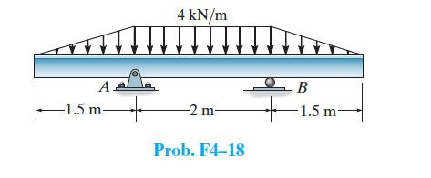
Draw the shear and moment diagrams for the beam. Indicate values at the supports and at the points where a change in load occurs. A -1.5 m- 4 kN/m -2 m Prob. F4-18 B -1.5 m-
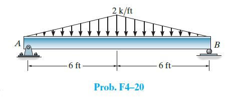
Draw the shear and moment diagrams for the beam. Indicate values at the supports and at the points where a change in load occurs. 6 ft- 2 k/ft Prob. F4-20 -6 ft- B
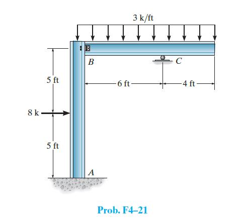
Draw the moment diagrams for the frame. Assume the frame is pin connected at B. 8 k 5 ft 5 ft B A 3 k/ft -6 ft- Prob. F4-21 C 4 ft
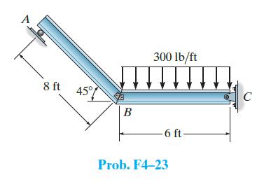
Draw the moment diagrams for the frame. Assume the frame is pinned at C and the members are fixed connected at B. A 8 ft 45° B 300 lb/ft -6 ft- Prob. F4-23 C
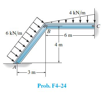
Draw the moment diagrams for the frame. Assume the frame is pin connected at A, B, and C. 6 kN/m -3 m B -6 m. 4 m 4 kN/m Prob. F4-24 C
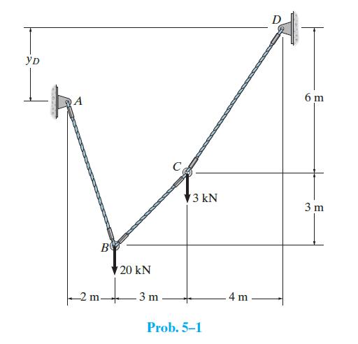
Determine the tension in each segment of the cable and the distance yD. yD B m 20 kN -3 m U 13 kN Prob. 5-1 4 m 6 m 3 m
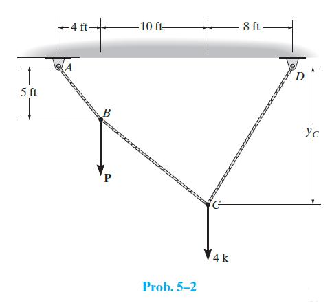
The cable supports the loading shown. Determine the magnitude of the vertical force P so that yC = 10 ft. 5 ft -4 ft- B P 10 ft- Prob. 5-2 4 k 8 ft D ус
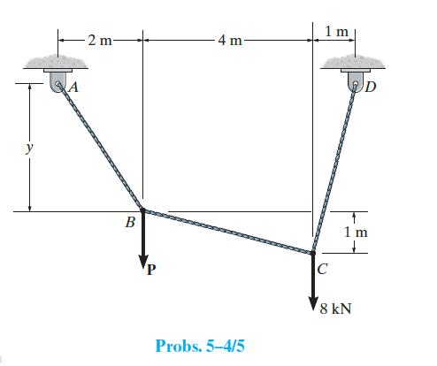
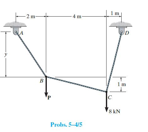
The cable supports the loading shown. Determine the distance y and the tension in cable BC. Set P = 3 kN. A 2 m B 4 m Probs. 5-4/5 1 m C D 1 m + 8 kN
The cable supports the loading shown. Determine the magnitude of the vertical force P so that y = 4 m. -2 m- A B -4 m- Probs. 5-4/5 1 m C D T 1 m 8 kN
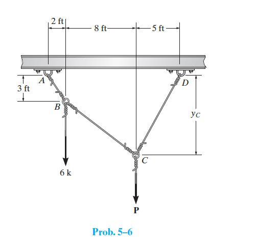
The cable segments support the loading shown. Determine the magnitude of the vertical force P so that yC = 6 ft. 3 ft 2 ft IB 6 k 8 ft- P Prob. 5-6 -5 ft- C D ус
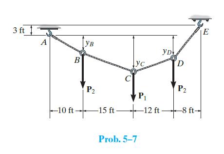
The cable supports the three loads shown. Determine the magnitude of P1 if P2 = 2 k, yB = 6 ft, and yC = 10 ft. Also find the sag yD. 31 A Bea B Ув C ус YD D Sax P2 P2 P₁₁ -106-15 - 12 n-+86- ft- Prob.5-7 E
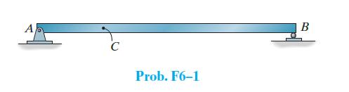
Use the Müller-Breslau principle to sketch the influence lines for the vertical reaction at A, the shear at C, and the moment at C. C Prob. F6-1 B
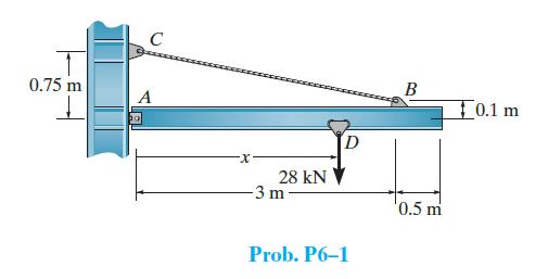
The chain hoist on the wall crane can be placed anywhere along the boom (0.1 m < x < 3.4 m) and has a rated capacity of 28 kN. Use an impact factor of 0.3 and determine the absolute maximum bending moment in the boom and the maximum force developed in the tie rod BC. The boom is pinned to the wall
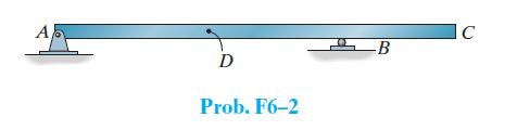
Use the Müller-Breslau principle to sketch the influence lines for the vertical reaction at A, the shear at D, and the moment at B. Al D Prob. F6-2 B C
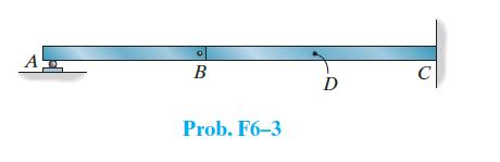
Use the Müller-Breslau principle to sketch the influence lines for the vertical reaction at A, the shear at D, and the moment at D. A B Prob. F6-3 D
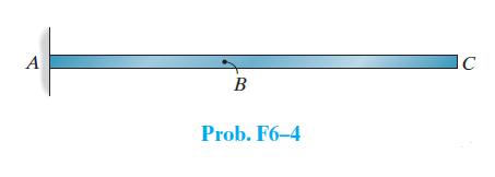
Use the Müller-Breslau principle to sketch the influence lines for the vertical reaction at A, the shear at B, and the moment at B. A B Prob. F6-4 C
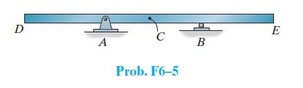
Use the Müller-Breslau principle to sketch the influence lines for the vertical reaction at A, the shear at C, and the moment at C. D A C Prob. F6-5 B E
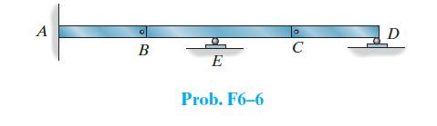
Use the Müller-Breslau principle to sketch the influence lines for the vertical reaction at A, the shear just to the left of the roller support at E, and the moment at A. A B E Prob. F6-6 0 C D
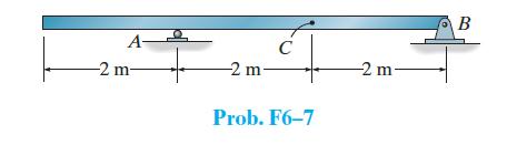
The beam supports a distributed live load of 1.5 kN/m and single concentrated load of 8 kN. The dead load is 2 kN/m. Determine (a) The maximum positive moment at C, (b) The maximum positive shear at C. A- -2 m- -2 m- C Prob. F6-7 -2 m B
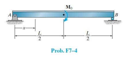
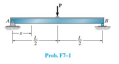
Determine the equation of the elastic curve for the beam using the x coordinate that is valid for 0 ≤ x ≤ L/2 and L/2 < x ≤ L. EI is constant.
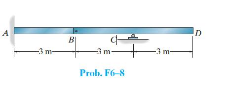
The beam supports a distributed live load of 2 kN/m and single concentrated load of 6 kN. The dead load is 4 kN/m. Determine (a) The maximum vertical positive reaction at C, (b) The maximum negative moment at A. A -3 m- B 다 -3 m Prob. F6-8 -3 m D
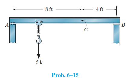
The beam is subjected to a uniform dead load of 200 lb/ft and a single live load of 5 k. Determine (a) The maximum moment created by these loads at C, and (b) The maximum positive shear at C. Assume A is a pin, and B is a roller. A 5 k 8 ft Prob. 6-15 C 4 ft B
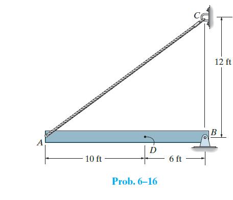
Draw the influence lines for (a) The force in the cable AC, (b) The vertical reaction at B, and (c) The moment at D. A 10 ft D Prob. 6-16 6 ft 12 ft B
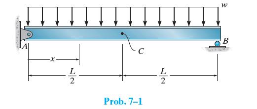
Determine the equation of the elastic curve using the coordinate x, and specify the slope at point A and the deflection at point C. EI is constant. -X L 2 C Prob. 7-1 L 2 W B
The beam supports a uniform dead load of 6 kN/m, a live load of 20 kN/m, and a single live concentrated force of 40 kN. Determine (a) The maximum positive moment at C, and (b) The maximum positive shear just to the right of the support at A. Assume A is a roller and B is a pin.
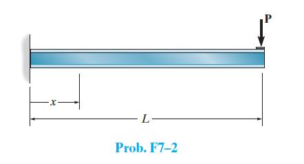
Determine the equation of the elastic curve for the beam using the x coordinate that is valid for 0 ≤ x ≤ L. EI is constant. -X -L- Prob. F7-2 P
Determine the equation of the elastic curve for the beam using the x coordinate that is valid for 0 ≤ x < L/2 and L/2 < x ≤ L. EI is constant.
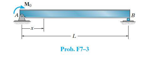
Determine the equation of the elastic curve for the beam using the x coordinate that is valid for 0 ≤ x ≤ L. EI is constant. Mo E ·X. -L- Prob. F7-3 B
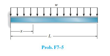
Determine the equation of the elastic curve for the beam using the x coordinate that is valid for 0 ≤ x ≤ L. EI is constant. ·X. W -L- Prob. F7-5
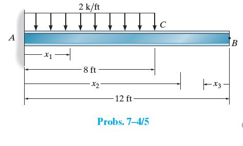
Determine the equations of the elastic curve using the coordinates x1 and x2 and specify the slope and deflection at B. EI is constant. A X1- 2 k/ft -8 ft ·x2- -12 ft- Jc Probs. 7-4/5 x3 B
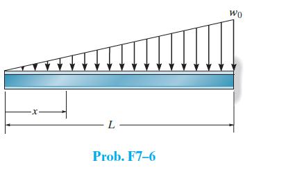
Determine the equation of the elastic curve for the beam using the x coordinate that is valid for 0 ≤ x ≤ L. EI is constant. -L- Prob. F7-6 WO
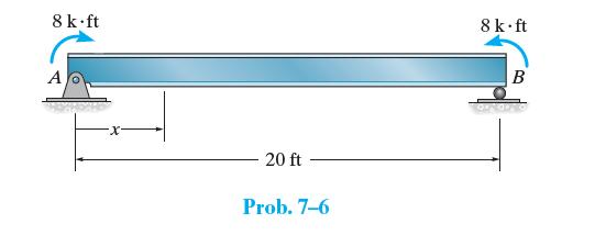
Determine the equation of the elastic curve for the beam using the x coordinate. Specify the slope at A and the maximum deflection of the beam. EI is constant. 8 k.ft A 20 ft Prob. 7-6 8 k.ft B
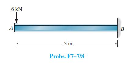
Use the moment-area theorems and determine the slope at A and deflection at A. EI is constant. 6 kN A 3 m- Probs. F7-7/8 B
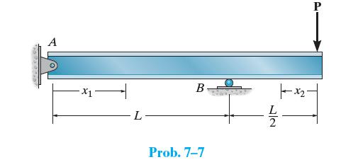
Determine the equations of the elastic curve for the beam using the x1 and x2 coordinates. Specify the beam’s maximum deflection. EI is constant. 1667 015 A -X1 L B Prob. 7-7 72 L |--x-₂-
Solve Prob. F7–7 using the conjugate-beam method.Data from Prob. F7–7Use the moment-area theorems and determine the slope at A and deflection at A. EI is constant. 6 kN A 3 m- Probs. F7-7/8 B
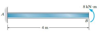
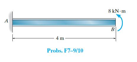
Use the moment-area theorems and determine the slope at B and deflection at B. EI is constant. A 4m- 8 kN-m B
Solve Prob. F7–9 using the conjugate-beam method.Data from Prob. F7–9Use the moment-area theorems and determine the slope at B and deflection at B. EI is constant. A 4 m- Probs. F7-9/10 8 kN.m B
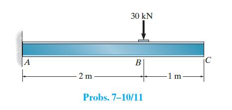
Determine the slope at B and the maximum displacement of the beam. Use the moment-area theorems. Take E = 200 GPa, I = 550(106) mm4. A 2m 30 kN ↓ B Probs. 7-10/11 -1 m- jc C
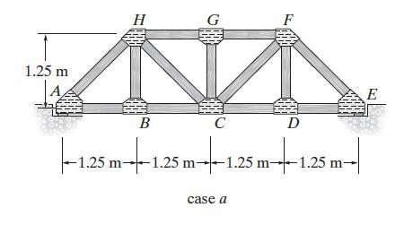
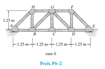
A simply supported pedestrian bridge is to be constructed in a city park and two designs have been proposed as shown in case a and case b. The truss members are to be made from timber. The deck consists of 1.5-m-long planks that have a mass of 20 kg/m2. A local code states the live load on the deck
Showing 300 - 400
of 363
1
2
3
4
Step by Step Answers