

A schematic diagram of a counter flow heat exchanger is shown in Figure 2.10. The hot fluid
Question:
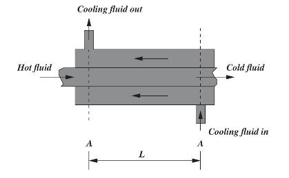
A schematic diagram of a counter flow heat exchanger is shown in Figure 2.10. The hot fluid enters the central, circular pipe from the left and exits at the right. The cooling fluid is circulated around the inner tube to cool the hot fluid. Using the principles of heat exchanger system discussed in chapter 9, construct a discrete system to determine the temperature distribution.
Fantastic news! We've Found the answer you've been seeking!
Step by Step Answer:

Answered By
Saad Farrukh
I Rohit here ,I have completed our Jee prepration from physics chemistry and math, that why love to solve ,math new problem as much as possible
0 Reviews
10+ Question Solved
Related Book For 

Fundamentals Of The Finite Element Method For Heat And Mass Transfer Wiley Series In Computational Mechanics
ISBN: 272391
2nd Edition
Authors: P. Nithiarasu, R. W. Lewis, K. N. Seetharamu
Question Posted:
