

Question: Consider the circuit in Figure P9.2. Draw the waveforms for the signals C, z 1 , and z 2 . Assume that C is a
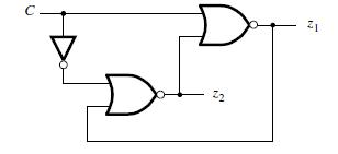
Consider the circuit in Figure P9.2. Draw the waveforms for the signals C, z1, and z2. Assume that C is a square-wave clock signal and that each gate has a propagation delayΔ. Express the behavior of the circuit in the form of a flow table that would produce the desired signals.
D 22 12
Step by Step Solution
★★★★★
3.45 Rating (164 Votes )
There are 3 Steps involved in it
1 Expert Approved Answer
Step: 1 Unlock

The circuit in Figure P92 consists of two AND gates and one OR gate The AND gates have inputs C an... View full answer
Question Has Been Solved by an Expert!
Get step-by-step solutions from verified subject matter experts
Step: 2 Unlock
Step: 3 Unlock