

Question: Give Verilog code for the sorting circuit designed in Problem 7.17. Data From Problem 7.17 The pseudo-code for the sorting operation given in Figure 7.40
Give Verilog code for the sorting circuit designed in Problem 7.17.
Data From Problem 7.17
The pseudo-code for the sorting operation given in Figure 7.40 uses registers A and B to hold the contents of the registers being sorted. Show pseudo-code for the sorting operation that uses only register A to hold temporary data during the sorting operation. Give a corresponding ASM chart that represents the data path and control circuits needed. Use multiplexers to interconnect the registers, in the style shown in Figure 7.42. Give a separate ASM chart that represents the control circuit.
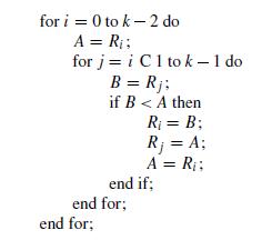
for i = 0 to k-2 do A = R : for j=i C1 tok - 1 do B = Rj; if B < A then end for; end for; R = B; R = A; A = R; end if;
Step by Step Solution
3.26 Rating (178 Votes )
There are 3 Steps involved in it
module sortinput 30 a ... View full answer

Get step-by-step solutions from verified subject matter experts