

Question: a. Use the subsystem block developed in Section 10.7 to construct a Simulink model of the system shown in Figure P30. The mass in flow
a. Use the subsystem block developed in Section 10.7 to construct a Simulink model of the system shown in Figure P30. The mass in flow rate is a step function.
b. Use the Simulink model to obtain plots of h1(t) and h2(t) for the following parameter values: A1 = 3 ft2, A2 = 5 ft2, R1 = 30 ft-1 ∙ sec-1, R2 = 40 ft-1 ∙ sec-1, ρ = 1.94 slug/ft3, qmi = 0.5 slug/sec, h1(0) = 2 ft, and h2(0) = 5 ft.
Figure P30
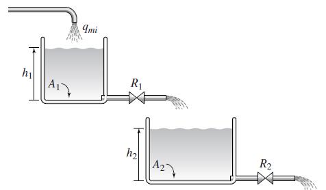
Imi hi A1 R1 R2 A2
Step by Step Solution
3.59 Rating (167 Votes )
There are 3 Steps involved in it
a In the following figure the model uses the mass inflow rate as a step function u... View full answer

Get step-by-step solutions from verified subject matter experts