

Question: Write a gate- level structural Verilog description for the circuit from Problem 4-11. Use the Verilog model for a D lip- lop from Figure 4-33.
Write a gate- level structural Verilog description for the circuit from Problem 4-11. Use the Verilog model for a D lip- lop from Figure 4-33.
Problem 4-11:
A sequential circuit has two D lip- lops, one input X, and one output Y. The logic diagram of the circuit is shown in Figure 4-49. Derive the state table and state diagram of the circuit.
Figure 4-49:
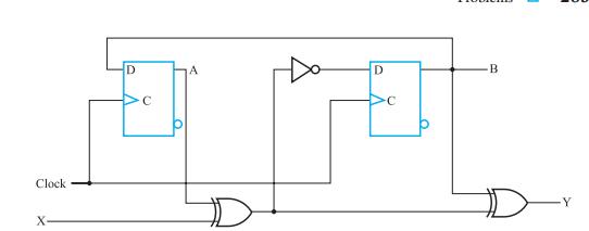
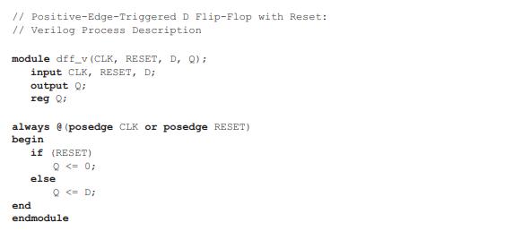
Figure 4-33:
Clock X D C A D B Y
Step by Step Solution
★★★★★
3.39 Rating (158 Votes )
There are 3 Steps involved in it
1 Expert Approved Answer
Step: 1 Unlock

The schematic in Figure 449 does not include a reset signal The m... View full answer
Question Has Been Solved by an Expert!
Get step-by-step solutions from verified subject matter experts
Step: 2 Unlock
Step: 3 Unlock