The circuit in Figure P32.96 represents your planned design for a wall power supply that will run
Question:
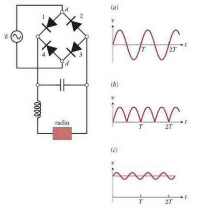
The circuit in Figure P32.96 represents your planned design for a wall power supply that will run a radio that usually runs on a 9-V battery. The power supply uses a transformer (not shown) to convert the \(110-\mathrm{V} \mathrm{AC}\) household emf of the wall outlet to a 9-V AC emf. If you do not add any additional components to this circuit, the potential difference over time is as shown in graph \(a\), a typical sinusoidally varying \(v(t)\) curve. Batteries supply direct current, however, and a radio designed to run on batteries cannot run on alternating current. If you address this problem by adding a rectifier to your circuit, the potential difference over time is as shown in graph \(b\). The radio still will not run properly, though, because the \(120-\mathrm{Hz}\) cycle would either render the radio dysfunctional or result in an annoying \(120-\mathrm{Hz}\) buzz. By adding a large capacitor in parallel with the rectifier, you can smooth out the potential difference as the capacitor charges and discharges over the course of a cycle. Still, there is going to be a residual \(120-\mathrm{Hz}\) "wiggle" on top of the DC signal, as shown in graph \(c\). You can filter out this wiggle by using an inductor as a low-pass filter. If the radio has an internal resistance of \(R=20.0 \Omega\), what inductance value do you need in order to reduce the wiggle by a factor of 2 ?
Data from Figure P32.96
Step by Step Answer:

This question has not been answered yet.
You can Ask your question!