

Question: Find a state machine diagram for a traffic light controller that works as follows: A timing signal T is the input to the controller. T
Find a state machine diagram for a traffic light controller that works as follows: A timing signal T is the input to the controller. T defines the yellow light interval, as well as the changes in the red and green lights. The outputs to the signals are defined by the following table:
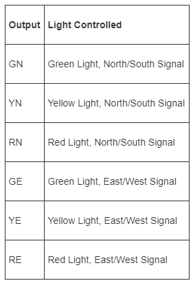
While T= 0, the green light is on for one signal and the red light for the other. With T= 1, the yellow light is on for the signal that was previously green, and the signal that was previously red remains red. When T becomes 0, the signal that was previously yellow becomes red, and the signal that was previously red becomes green. This pattern of alternating changes in color continues. Assume that the controller is synchronous with a clock that changes much more frequently than input T.
Output Light Controlled GN YN RN GE YE RE Green Light, North/South Signal Yellow Light, North/South Signal Red Light, North/South Signal Green Light, East/West Signal Yellow Light, East/West Signal Red Light, East/West Signal
Step by Step Solution
3.43 Rating (150 Votes )
There are 3 Steps involved in it
To create a state machine diagram for the traffic light controller described we need to define the s... View full answer

Get step-by-step solutions from verified subject matter experts