

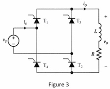
The controlled full-wave bridge rectifier of Fig. 3 has a source of 120 V rms at 60
Fantastic news! We've Found the answer you've been seeking!
Question:
The controlled full-wave bridge rectifier of Fig. 3 has a source of 120 V rms at 60 Hz and an R-L load, where R=12 ohm and L=110 m11. The delay angle is equal to 50 degrees.
a. Determine the dc (average) component of the current.
b. Determine the power absorbed by the load. Use equations (1) and (2) in tutorial notes.
Expert Answer:

Related Book For 
Electronic Devices and Circuit Theory
ISBN: 978-0135026496
10th edition
Authors: Robert L. Boylestad, Louis Nashelsky
Posted Date:
