

The tank as shown in Figure comprises two cylindrical shaped closed subsystems A and B. The tank
Question:
The tank as shown in Figure comprises two cylindrical shaped closed subsystems A and B. The tank is completely insulated. A frictionless piston separates the two subsystems. The Subsystem A contains 9 x 10 -3 m 3 of liquid water - vapour mixture with a quality of 85 percent at the pressure of 125 kPa. The piston has a cross- sectional area of 60 cm 2 . The subsystem B contains 0.1 kg of air with the pressure and temperature of 100 kPa and 30?C, respectively. A 15 W heating coil is placed inside the subsystem. A causing the piston to move up and push the stopper. The final pressure of subsystem A is 300 kPa. No heat is transferred from subsystem A to subsystem 13 through the piston. You may assume air as ideal gas. For air, the ideal gas constant (R) is given as 0.287 kJ/kg. K. The specific heat capacity at constant pressure (cp) is 1.008 kJ/kg. K and the specific heat at constant volume (c,) is 0.721kJ/kg. K.
(a) Calculate the initial temperature and the mass of water vapour at subsystem A. what is the final temperature of subsystem B? Draw the p-v diagram for subsystem B and show how the states changes from initial to final.
(b) Define the state at which the piston just touches the stopper.
(c) Calculate the work done by subsystem A up to the final state. Show the process in P-v diagram.
(d) Calculate the required time to power the heating coil for the final pressure of 300 kPa (for subsystem A) 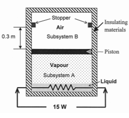
Expert Answer:
Given in substance A state 1A Dryness fraction x 085 Pressure P 1 A 125 x 10 3 Pa Volume V 1 A 9 x 10 3 m 3 Working fluid A r Mass of air M 1B 01 kg P... View the full answer


Introduction to Statistical Quality Control
ISBN: 978-1118146811
7th edition
Authors: Douglas C Montgomery
